 ENEnglish
 VITiếng Việt
 ZH中文
 KO한국어
 JA日本語
 FRFrançais
 ITItaliano
 PTPortuguês
 ESEspañol
 HEעברית
 ARالعربية

 plans · elevations
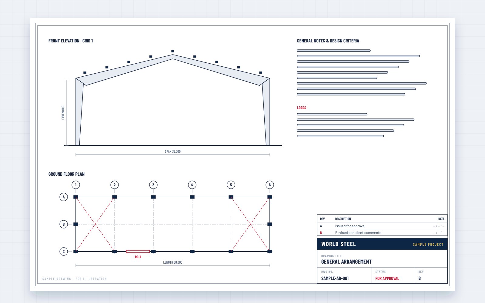
General arrangement
Floor and roof plans, elevations and grid lines with overall dimensions, openings, doors and accessories, plus general notes and design criteria.
Solution · Approval drawings
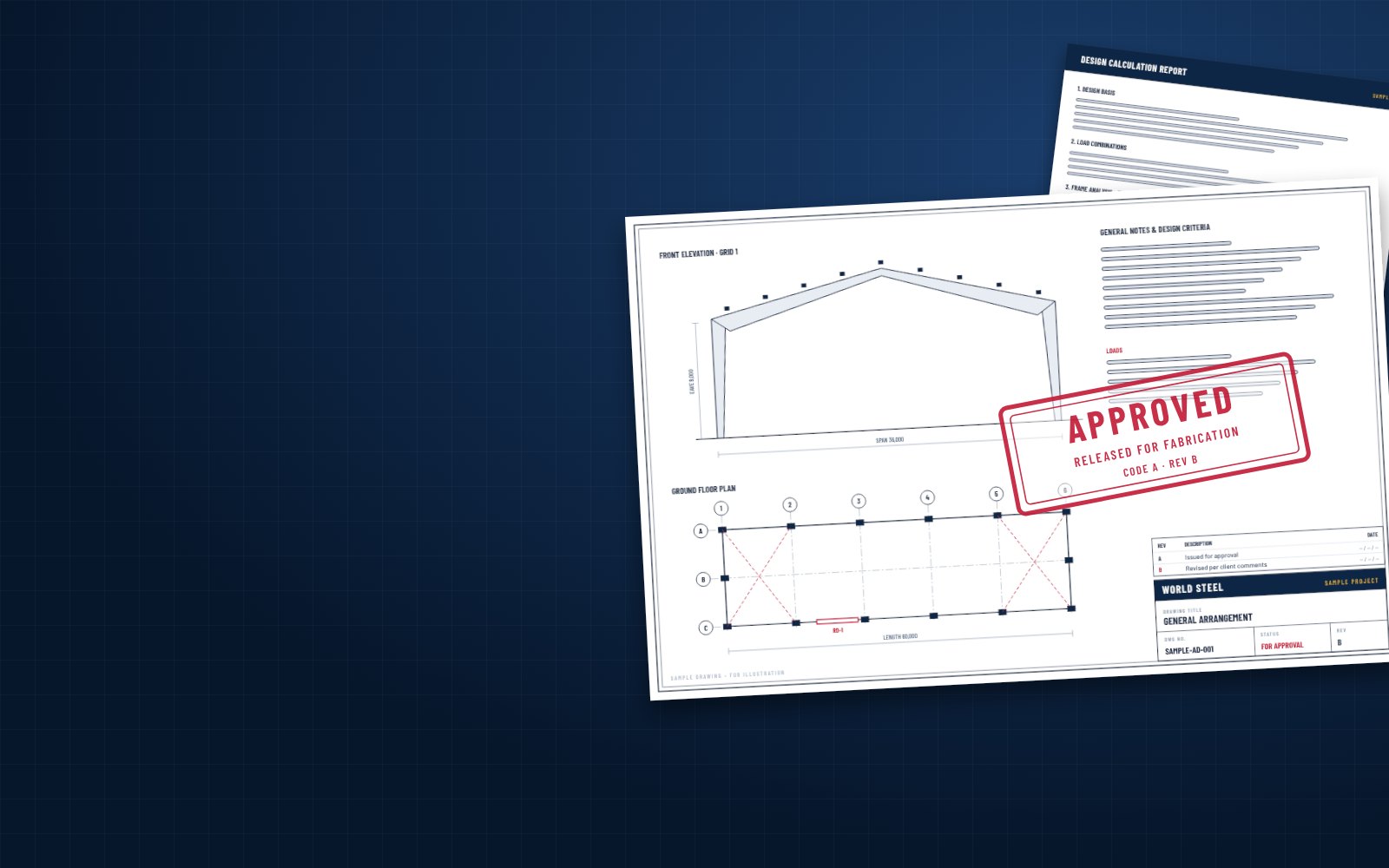
Before a single plate is cut, you see exactly what we will build: approval drawings, the design report with the calculations behind them, and the column reactions your foundation engineer needs. Nothing goes to the shop floor until you or your engineer have approved it.
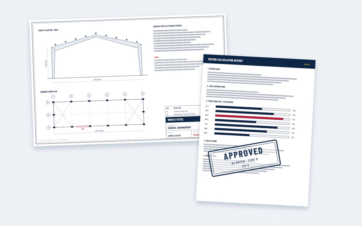
Approval drawings – also called general arrangement (GA) or “for approval” drawings – are the first formal drawing set of a steel project. They translate the contract, the design basis and the engineering into drawings you can check: building geometry, grid lines, frame cross-sections, roof and wall framing, bracing, openings, anchor bolt layout with column reactions, typical connections, materials, coatings, and the design codes and loads used.
They are issued together with the design calculations, reviewed by you, your architect or your engineer of record, and returned with a status. Only drawings marked approved are released to fabrication; shop drawings, CNC data and erection drawings are then produced from the approved set. Under the AISC Code of Standard Practice, approval confirms that the fabricator has correctly interpreted the contract documents and releases the drawings for fabrication – the fabricator remains responsible for detailed dimensions and fit-up.
Contents of the set
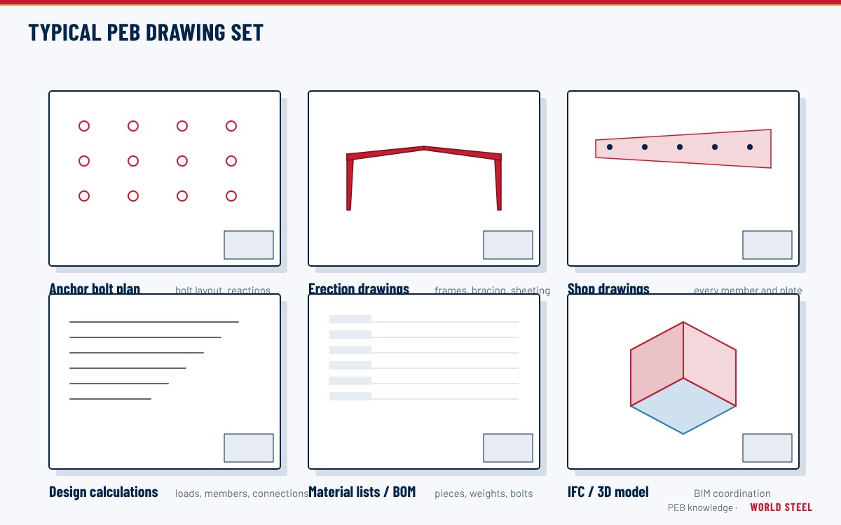
A typical set for a steel building or pre-engineered building – the exact sheets depend on the structure and the market.
plans · elevations
Floor and roof plans, elevations and grid lines with overall dimensions, openings, doors and accessories, plus general notes and design criteria.
 for foundations
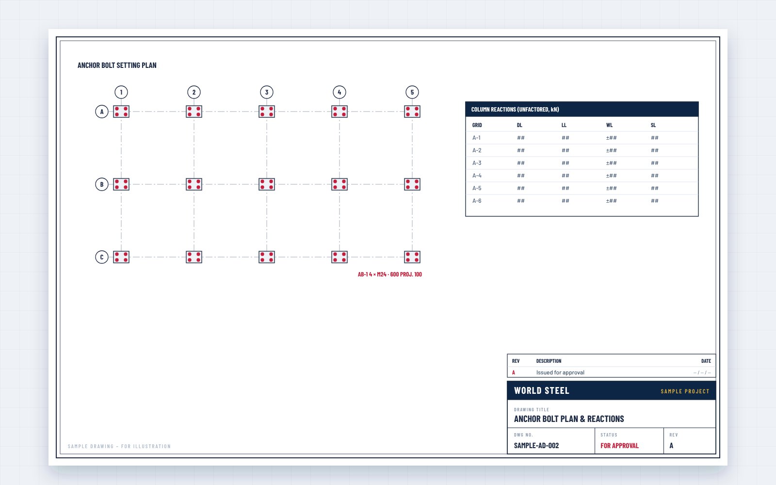
Bolt layout, diameters, projections and base plate orientation, with unfactored column reactions by load case for the foundation designer.
 member marks
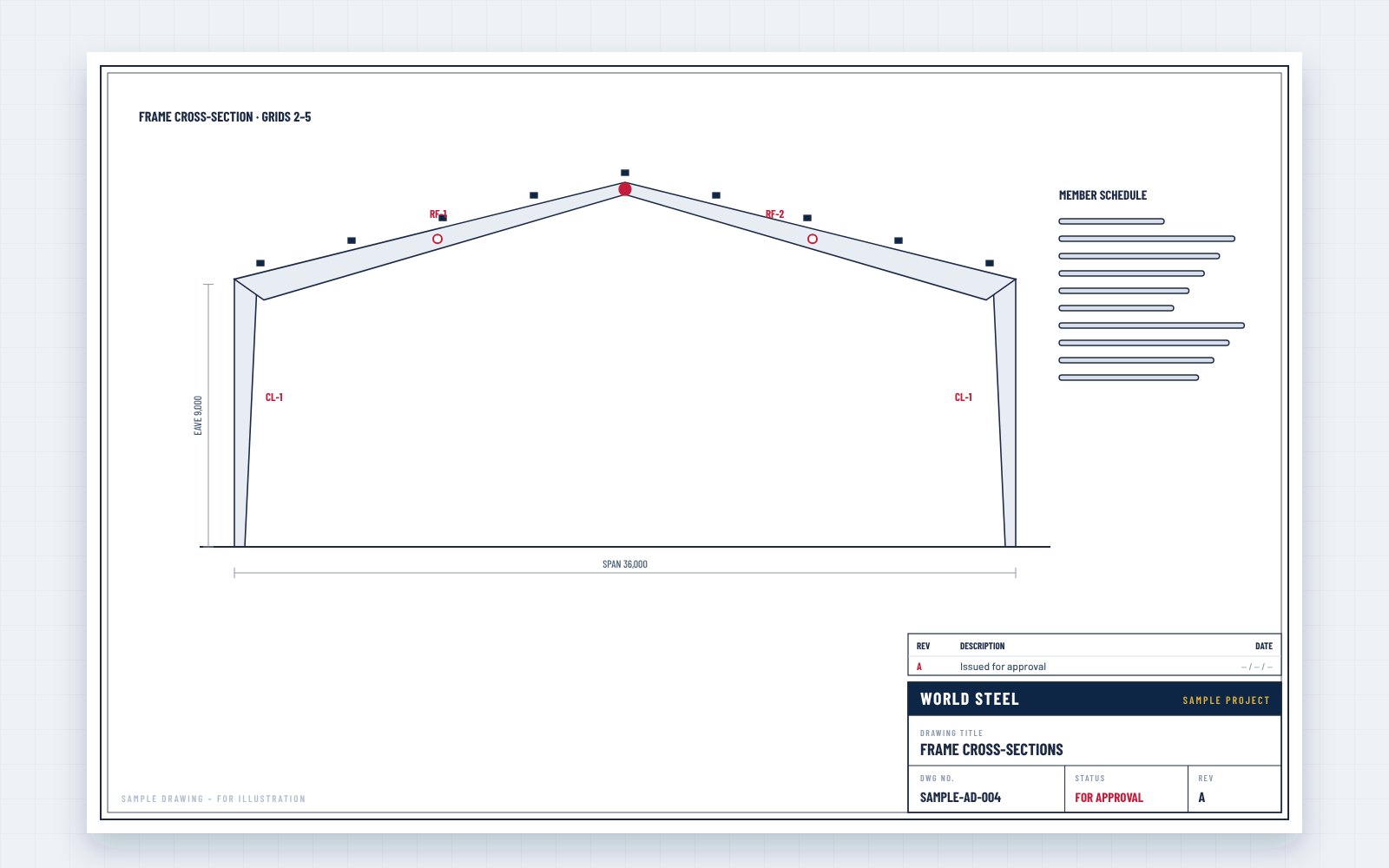
Each frame type with member marks, sizes, splices, eave height, roof slope and clear dimensions.
 bracing · purlins
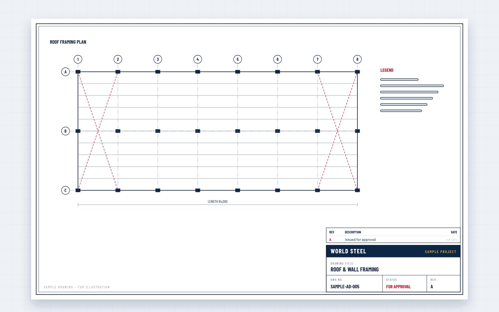
Purlin and girt layouts, roof and wall bracing, sag rods, framed openings and endwall framing.
 typical details
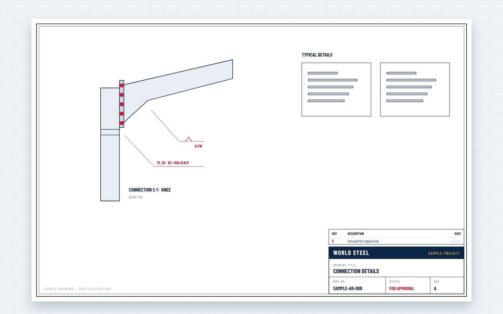
Knee, apex, splice and base connections with plate thicknesses, bolt grades and weld sizes.
 loads · checks
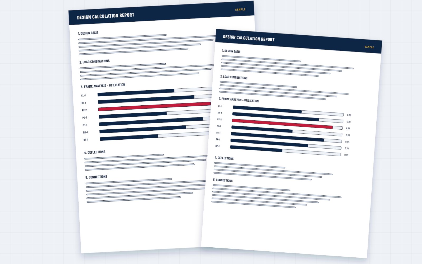
Design basis, load combinations, frame analysis, member and connection checks, deflections – submitted with the drawings.
Ứng dụng
Spans, heights, openings, cranes and accessories are confirmed on paper – where a change costs an eraser, not a re-fabricated frame.
You see the loads, codes, member sizes, utilisations and connection details we designed – nothing is hidden in the steel.
Your engineer of record or certifier can verify the design against local codes before anything is built.
The anchor bolt plan and unfactored column reactions let your civil contractor design and pour foundations while steel is fabricated.
Owner, architect, foundation contractor, fabricator and erector work from the same approved revision.
Approved drawings are the agreed record of what was ordered – the basis for inspection, variations and as-built records.
Tiêu chuẩn & tuân thủ
Approval drawings state the design codes, loads, materials and execution class on their general notes – and are prepared to the drafting and fabrication standards of your market.
 International drafting
 United States
 Australia & New Zealand
 Europe
Nội dung chỉ mang tính tham khảo – chỉ dẫn kỹ thuật của dự án, phiên bản quy chuẩn được áp dụng và cơ quan có thẩm quyền là căn cứ quyết định.
With every submission
A complete, traceable package – so your reviewer can check the design, not chase information.
Every issue
List of sheets with numbers, titles, revisions and status, so nothing is missed or superseded.
Plans · elevations
Geometry, grid lines, openings, accessories, general notes and design criteria.
For foundations
Bolt layout and details with unfactored column reactions by load case.
Structure
Frame cross-sections, roof and wall framing, bracing and member marks.
Connections
Plates, bolts and welds for the main connections.
Engineering
Design basis, loads and combinations, analysis, member and connection checks, deflections.
Specification
Steel grades, bolt grades, coating system and finishes as agreed in the contract.
From revision B
Each review comment with our answer and the revision in which it was closed.
Contents vary with the project and market; sheets and calculations are issued as PDF, with DWG or IFC files on request.
Quy trình thiết kế World Steel
Điểm dừng sau bước 2: không chế tạo bất kỳ cấu kiện nào trước khi bản vẽ Approval được phê duyệt.
Design workflow · step 2 of 6
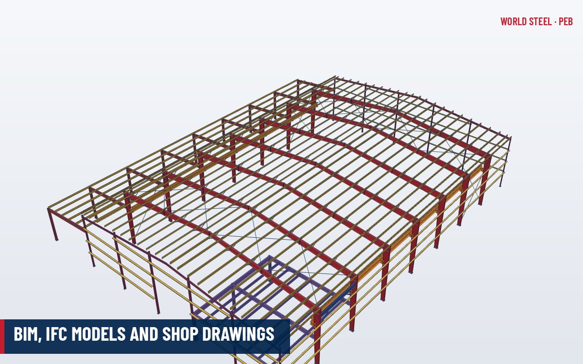
Approval is step 2 of the six-step World Steel design workflow – after the proposal drawings (PPD) and the contract, and before the 3D Tekla model, shop drawings, erection drawings and as-built drawings. The approval package has three parts: the approval drawings, the design report and the column reactions.
Design report & column reactions
The design report sets out the design basis – codes, loads and combinations, materials – and the analysis and checks of frames, members, connections and deflections, so your engineer can verify the design. The column reactions give the unfactored support forces at every column base by load case, with the anchor bolt plan, so the foundation designer can design and the civil contractor can build the foundations while the steel is fabricated.
Before the first line · Design basis
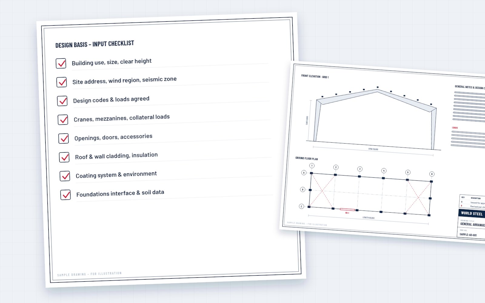
Approval drawings are only as good as their inputs. Before drawing starts, our engineers confirm the design basis with you: building use and dimensions, site location and climate data, design codes and loads, cranes and collateral loads, openings and accessories, cladding, coating system and the foundation interface.
Anything missing or unclear is listed in a query sheet – we do not guess on your behalf. The agreed design basis is printed on the general notes of every set.
Review · Status codes
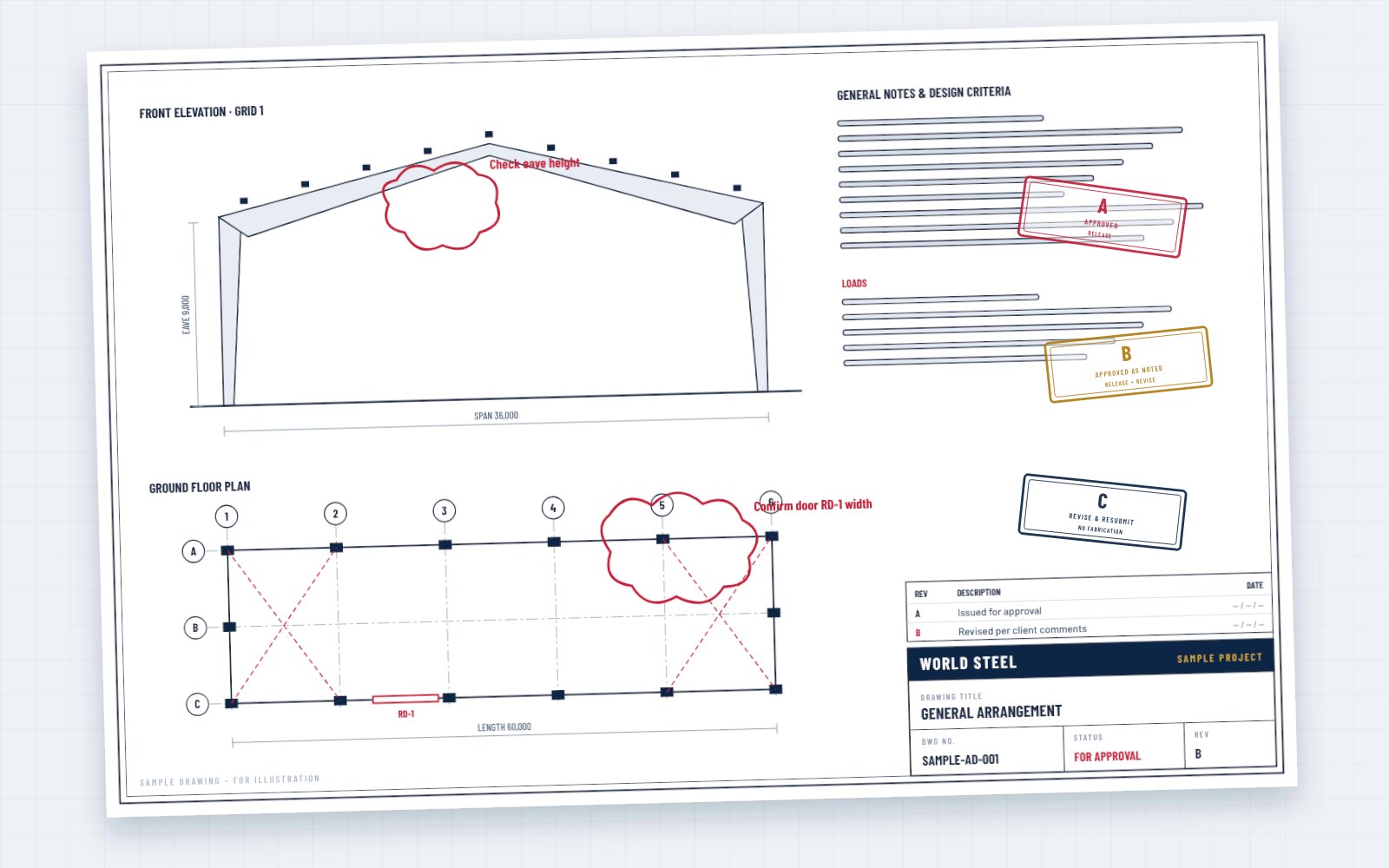
Every submission goes out with a transmittal and drawing register. Your reviewer returns each sheet with a status: A – approved, B – approved as noted (released, comments incorporated in the next revision) or C – revise and resubmit (no fabrication).
We answer every comment on a comment response sheet, cloud each change on the drawing and raise the revision letter – so you can see exactly what changed between issues.
Hold point · Release
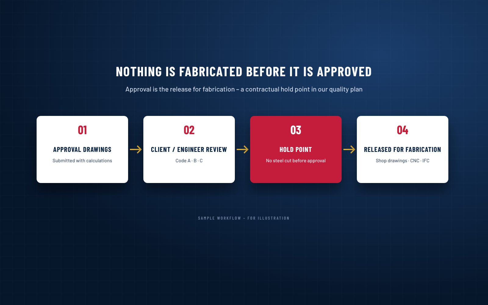
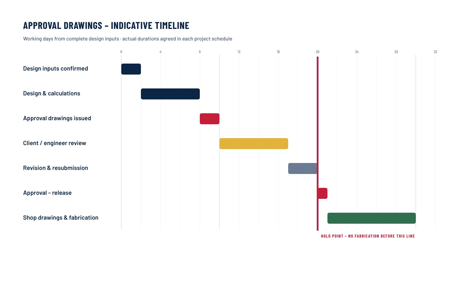
Approval is a hold point in our quality plan. Material may be reserved, but no steel is cut, drilled or welded for a member until the drawing that shows it is approved (code A or B).
Once released, the approved set becomes the single reference for shop drawings, CNC data, the 3D model, QA/QC inspection and erection drawings. Changes after approval go through a formal revision and are agreed with you before they reach the shop floor.
Compliance
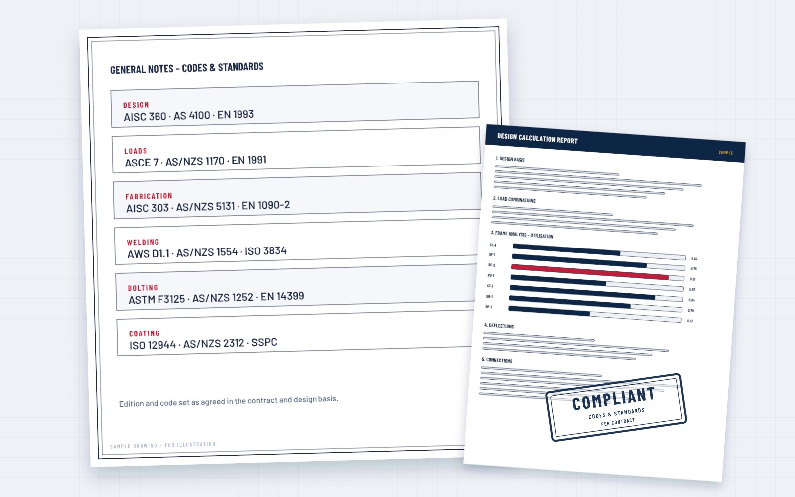
The general notes state the design codes and editions, loads, materials, bolt grades, welding and coating standards and the execution class or construction category agreed in the contract – US, Australian and New Zealand, European or other national codes.
Where the authority requires design certification or sealed drawings, we coordinate with the licensed engineer for the project. Approval drawings let your engineer confirm compliance before fabrication – not after delivery.
Timing
For a typical pre-engineered building, approval drawings and calculations are usually issued within one to two weeks of complete design inputs; complex structural steel projects take longer. Review time is set in your contract – AISC 303 assumes 14 calendar days if nothing else is agreed – and revised drawings are normally reissued within a few working days of receiving comments.
The fastest projects are the ones with complete inputs and one consolidated set of comments. Exact durations are agreed in each project schedule.
Reference
How approval works in practice – indicative values; your contract and project schedule govern.
| Code | Status | What happens next |
|---|---|---|
| A | Approved | Released for fabrication; shop drawings and production start |
| B | Approved as noted | Released for fabrication with the noted corrections; corrections shown in the next revision |
| C | Revise and resubmit | Not released – drawings revised, clouded and resubmitted for approval |
| Stage | Typical duration | Notes |
|---|---|---|
| Design inputs confirmed | 1–2 working days | Query sheet for anything missing |
| Approval drawings & calculations – PEB | About 1–2 weeks | From complete design inputs |
| Approval drawings & calculations – complex structural steel | About 2–4 weeks | Depends on size, connections and codes |
| Client / engineer review | As per contract | AISC 303 default: 14 calendar days |
| Revision & resubmission | A few working days | After one consolidated set of comments |
| Anchor bolt plan | With or right after approval | So foundations can start early |
| Drawing | Purpose | Reviewed by |
|---|---|---|
| Approval (GA) drawings | Confirm scope, geometry, design and codes | Owner, architect, engineer of record |
| Anchor bolt plan | Foundation design and bolt setting | Foundation designer, civil contractor |
| Shop (fabrication) drawings | Make every part – plates, holes, welds, piece marks | Fabricator QA/QC (client on request) |
| Erection drawings | Assemble the structure on site | Erector and site supervisor |
Quy trình
Contract drawings, specifications and site data collected; codes, loads, materials and execution class agreed – open points in a query sheet.
Frames, members and connections designed and optimised to the agreed codes.
General arrangement, anchor bolts, frames, framing and details prepared with the calculation report, checked against the design basis.
Issued for approval with transmittal and drawing register.
Returned with status A, B or C; comments answered, changes clouded, revision raised.
Approved set released – anchor bolt plan, shop drawings and fabrication follow.
FAQ
Approval drawings show what will be built – geometry, frames, connections, loads and codes – for you or your engineer to approve. Shop drawings are produced afterwards from the approved set and show how each individual part is made in the factory.
No. Approval is a hold point in our quality plan: steel for a member is cut only after the drawing that shows it is approved (code A or B). Material may be reserved in advance to protect the schedule.
The owner confirms scope and geometry; the architect checks layout and openings; the engineer of record or certifier checks the design against the local codes. One consolidated set of comments keeps the schedule short.
For a typical pre-engineered building we usually issue approval drawings within one to two weeks of complete design inputs. Review time is set in the contract – AISC 303 assumes 14 calendar days if nothing else is agreed.
Changes after approval are issued as a new revision, clouded on the drawings, and their effect on cost and schedule is agreed with you before fabrication of the affected members.
Yes. The calculation report – design basis, loads, analysis, member and connection checks and deflections – is submitted with the approval drawings so your engineer can verify the design.
Where the authority requires sealed drawings or design certification, we coordinate with the licensed engineer for the project and agree this in the contract.
Send us your architectural drawings or design brief – we confirm the design basis and plan the approval schedule with your quotation.