 ENEnglish
 VITiếng Việt
 ZH中文
 KO한국어
 JA日本語
 FRFrançais
 ITItaliano
 PTPortuguês
 ESEspañol
 HEעברית
 ARالعربية

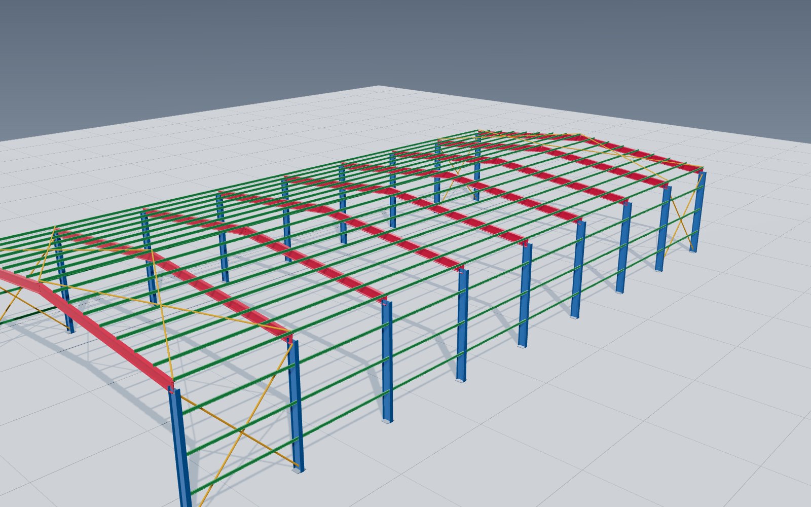 LOD fabrication
Full structural model
Primary and secondary steel, bracing and connections, coloured by member class.
Design workflow · 3D Tekla model
After approval, our detailers build the structure in Tekla Structures: every member, plate, bolt and weld in its exact position, checked for clashes, sequenced for erection – and the single source of shop drawings, CNC data, material lists and erection drawings.
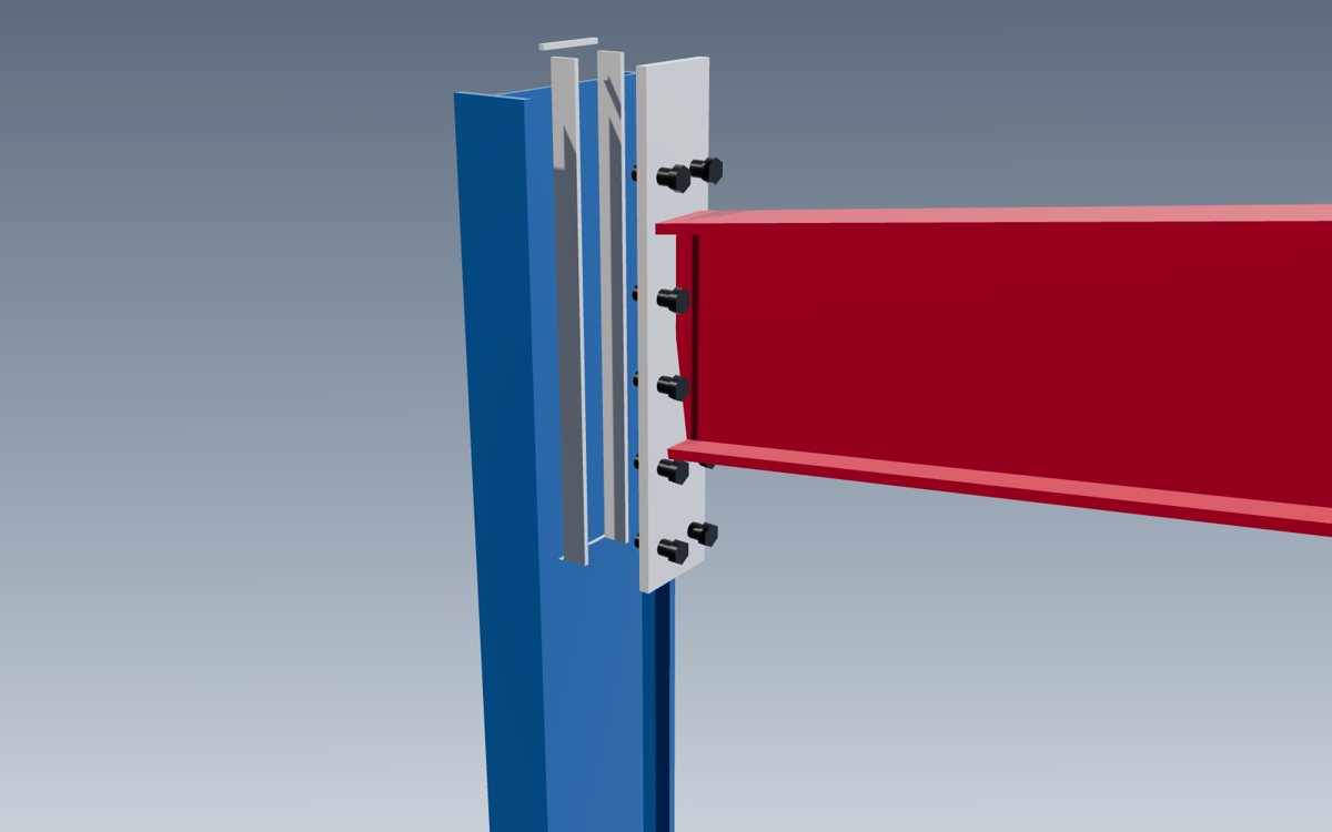
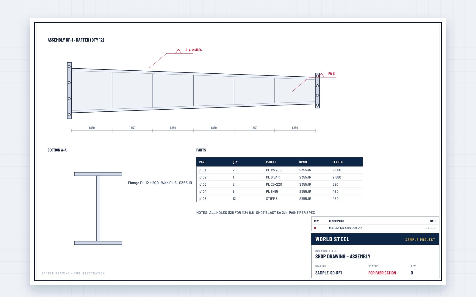
Once the approval drawings are approved, the structure is built again – digitally. In Tekla Structures our detailers model every member, connection plate, stiffener, bolt and weld at fabrication level, exactly as it will be made.
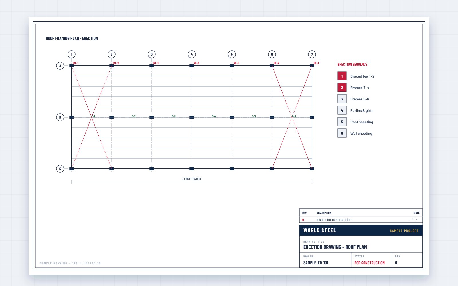
The model is checked for clashes with itself and with architectural and MEP models, organised by erection phase, and then used to generate everything the factory and the site need: assembly and part drawings, CNC files for cutting and drilling, bills of materials and erection drawings. When something changes, it changes once – in the model.
Model uses
From coordination to the shop floor and the site.
LOD fabrication
Primary and secondary steel, bracing and connections, coloured by member class.
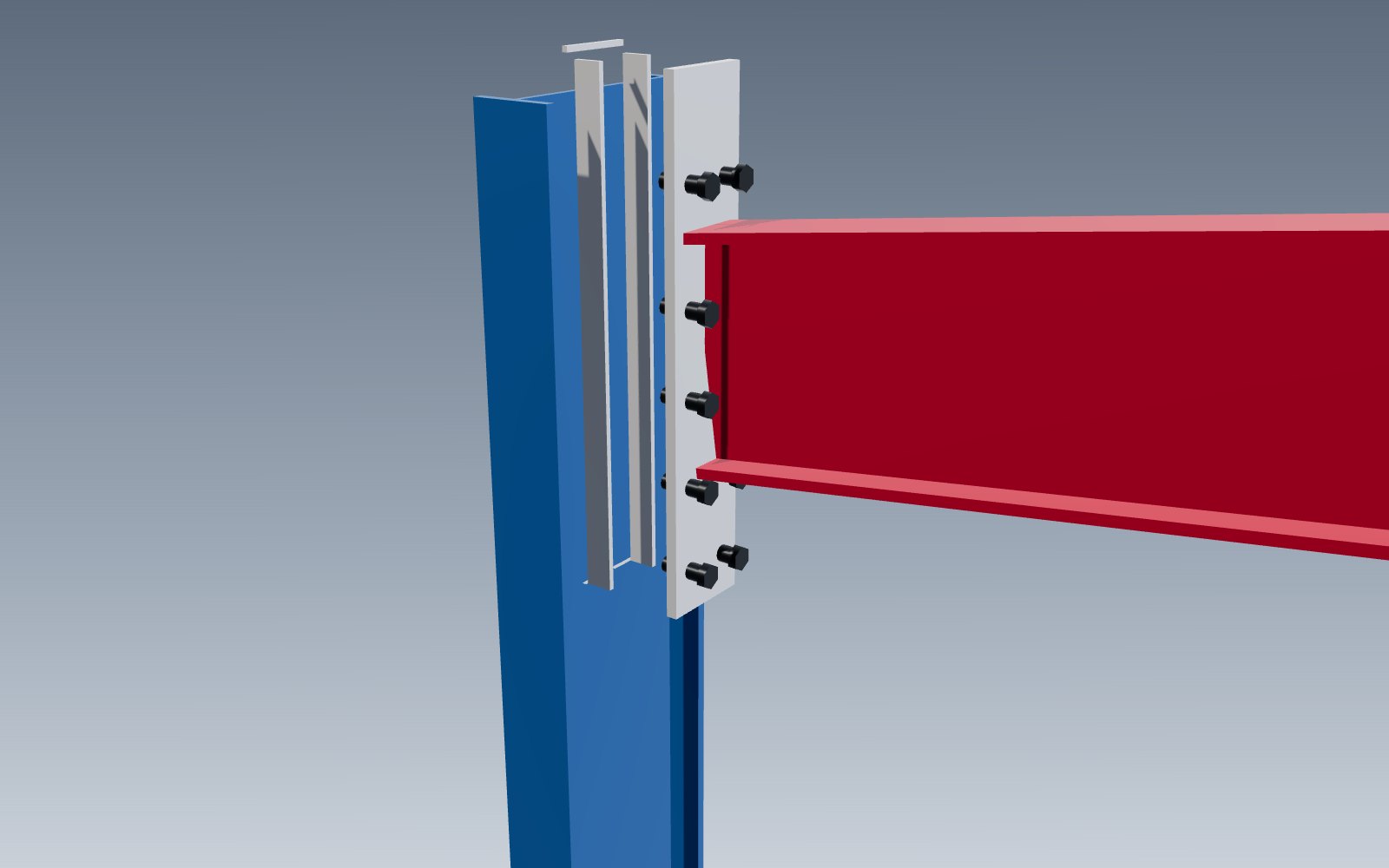 plates · bolts · welds
End plates, stiffeners, splices and base plates detailed to the approved design.
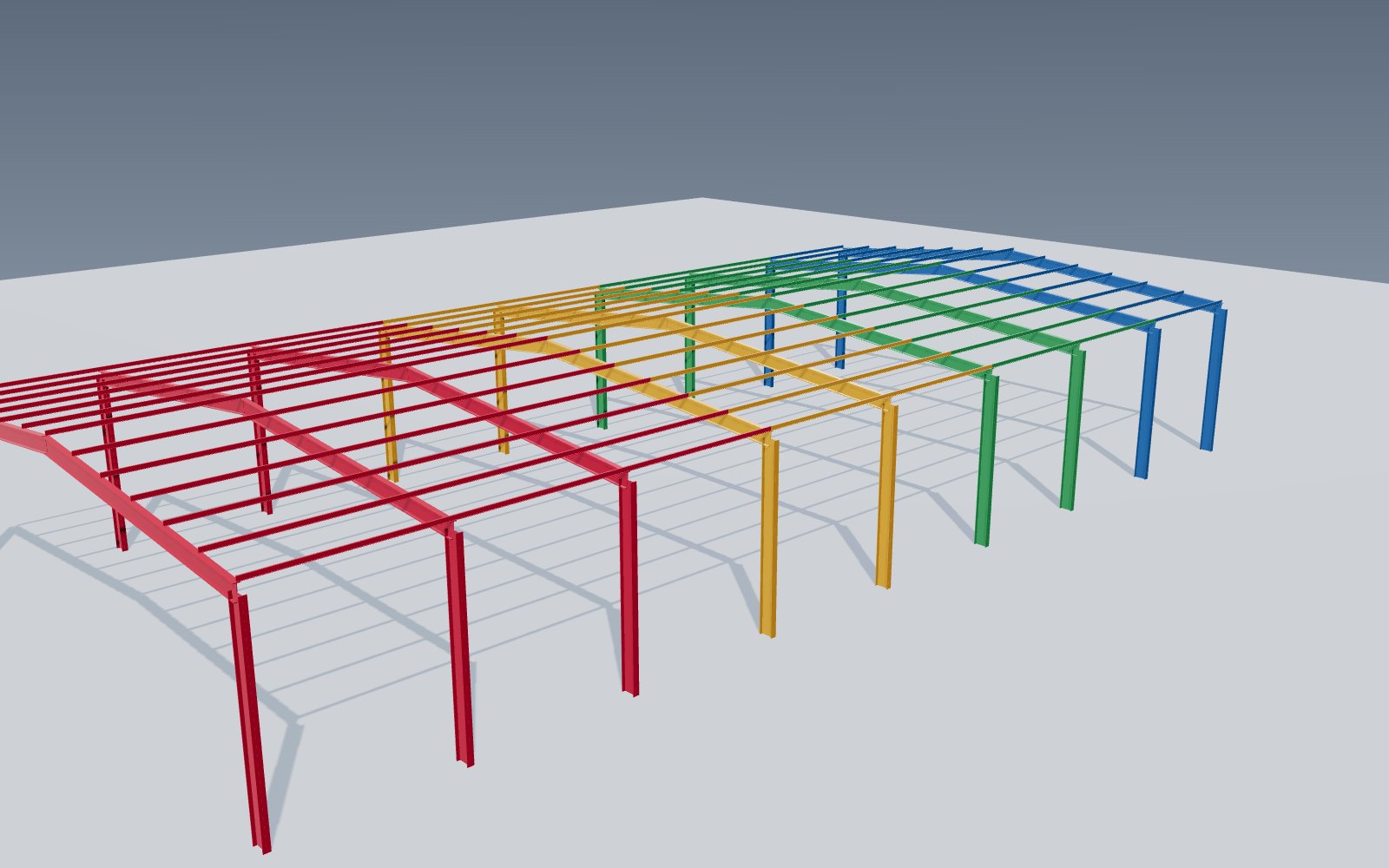 sequence
Members grouped by erection phase for shipping, delivery and site planning.
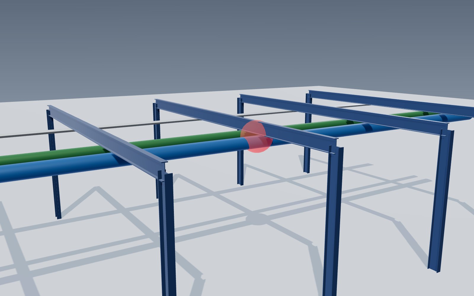 coordination
Steel checked against MEP, equipment and architecture before release.
 production
Assembly and part drawings, NC files and nesting from the model – see shop drawings.
 site
Plans, sections and bolt lists generated from the model – see erection drawings.
应用领域
Connections, bolts and clearances checked in 3D before a single piece is cut.
Steel coordinated with architecture, MEP, cranes and equipment.
Shop and erection drawings come from the model – consistent and up to date.
Cutting and drilling data exported directly to our machines.
Material lists and weights from the model, not estimates.
IFC export for your design team, viewable in any IFC viewer.
Design workflow · step 3 of 6
The 3D model is step 3 of our six-step design workflow. It starts from the approved drawings and design report, and it produces the shop drawings (step 4), the erection drawings (step 5) and, updated with site changes, the as-built record (step 6).
World Steel 设计流程
第 2 步后设停检点:报批图纸获批前不进行任何加工。
Open BIM
We export the model as IFC – the open BIM standard ISO 16739 – so architects, MEP engineers and owners can review and coordinate it in their own software or a free IFC viewer. Selected project models are also published in the 3D viewer on our project pages.
流程
Layout, sections and preliminary quantities issued with the quotation.
Approval drawings, design report and column reactions – approved before fabrication.
Every member, plate, bolt and weld modelled and clash-checked.
Assembly and part drawings, CNC data and material lists.
Plans, sections, sequence and bolt lists for site.
Final record of the structure as built.
FAQ
Tekla Structures for 3D detailing, with IFC export for coordination with other BIM software.
Yes – an IFC export can be provided for coordination; native files are agreed in the contract.
Yes. Send us your IFC models and we coordinate the steel before shop drawings are released.
Yes. Every approved change is made in the model first, and drawings and CNC data are regenerated from it.
Send us your approved design or BIM models – we model, coordinate and detail the steel and deliver drawings and CNC data from one source.