 ENEnglish
 VITiếng Việt
 ZH中文
 KO한국어
 JA日本語
 FRFrançais
 ITItaliano
 PTPortuguês
 ESEspañol
 HEעברית
 ARالعربية

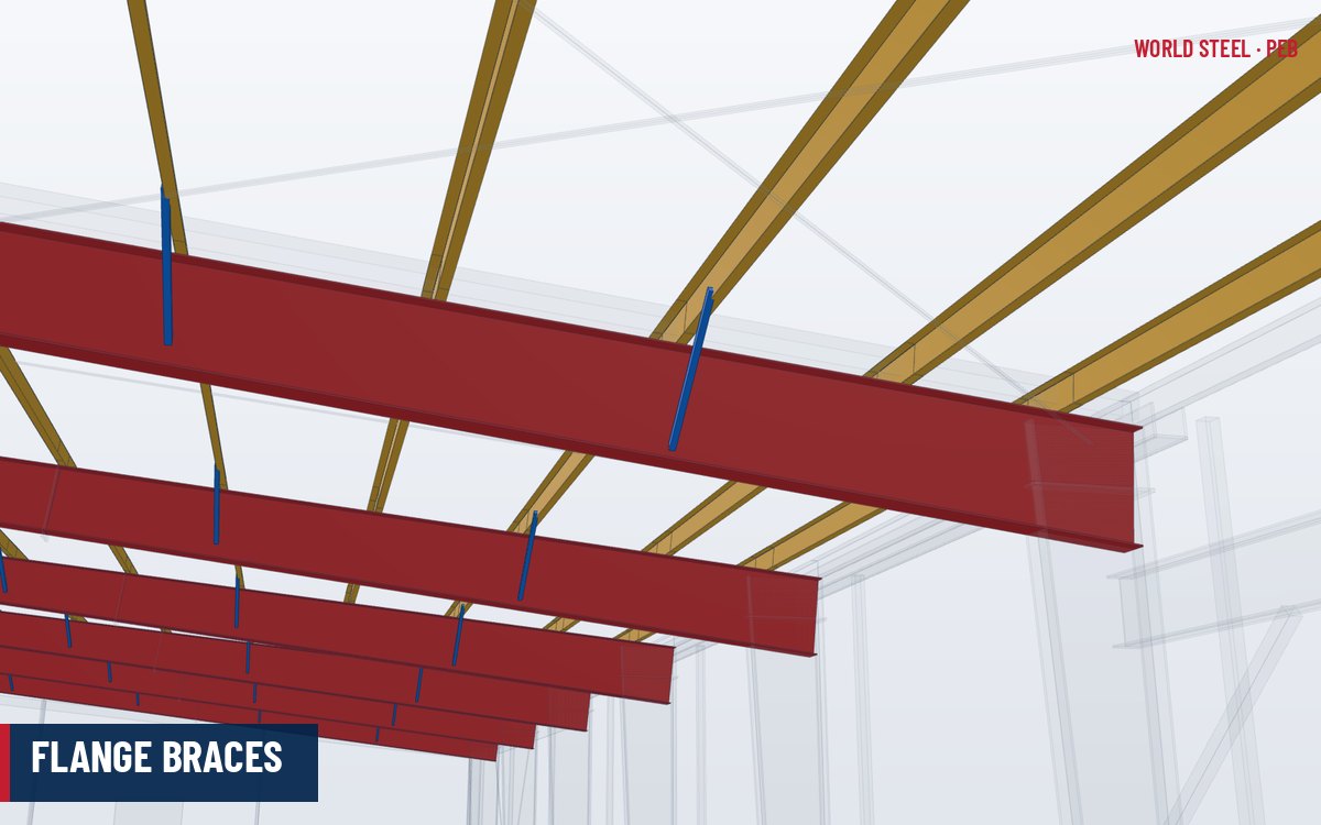
What a flange brace is
A flange brace is a short diagonal member, usually a small steel angle, that connects the inner (inside) flange of a rafter or column to a nearby purlin or girt. It prevents the inner flange from moving sideways, which restrains the frame against lateral-torsional buckling.
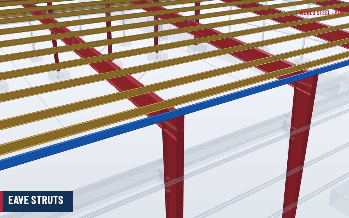
The outer flange of a frame member is held by the purlins or girts bolted to it. The inner flange has no direct attachment, yet under many load cases it is the compression flange: near the knee under gravity load, and along much of the rafter under wind uplift. Flange braces are therefore essential – a frame designed with flange bracing has a much lower capacity if the braces are left out.
How flange braces fit the load path
Flange braces do not carry primary loads. Instead they enable the primary frame to carry its loads by limiting the unbraced length of the compression flange. The small brace force – typically a percentage of the flange compression force – travels through the brace to the purlin or girt, then along the secondary members into the roof or wall diaphragm and bracing system.
Typical sizes and materials
| Item | Typical |
|---|---|
| Section | Equal angle L40×40 to L65×65, 3–6 mm; or cold-formed angle |
| Configuration | Single brace one side, or pair both sides |
| Angle to member | About 45°, varies with purlin depth and member depth |
| Bolts | M12 or M16, one per end |
| Finish | Galvanised or painted to match the frame |
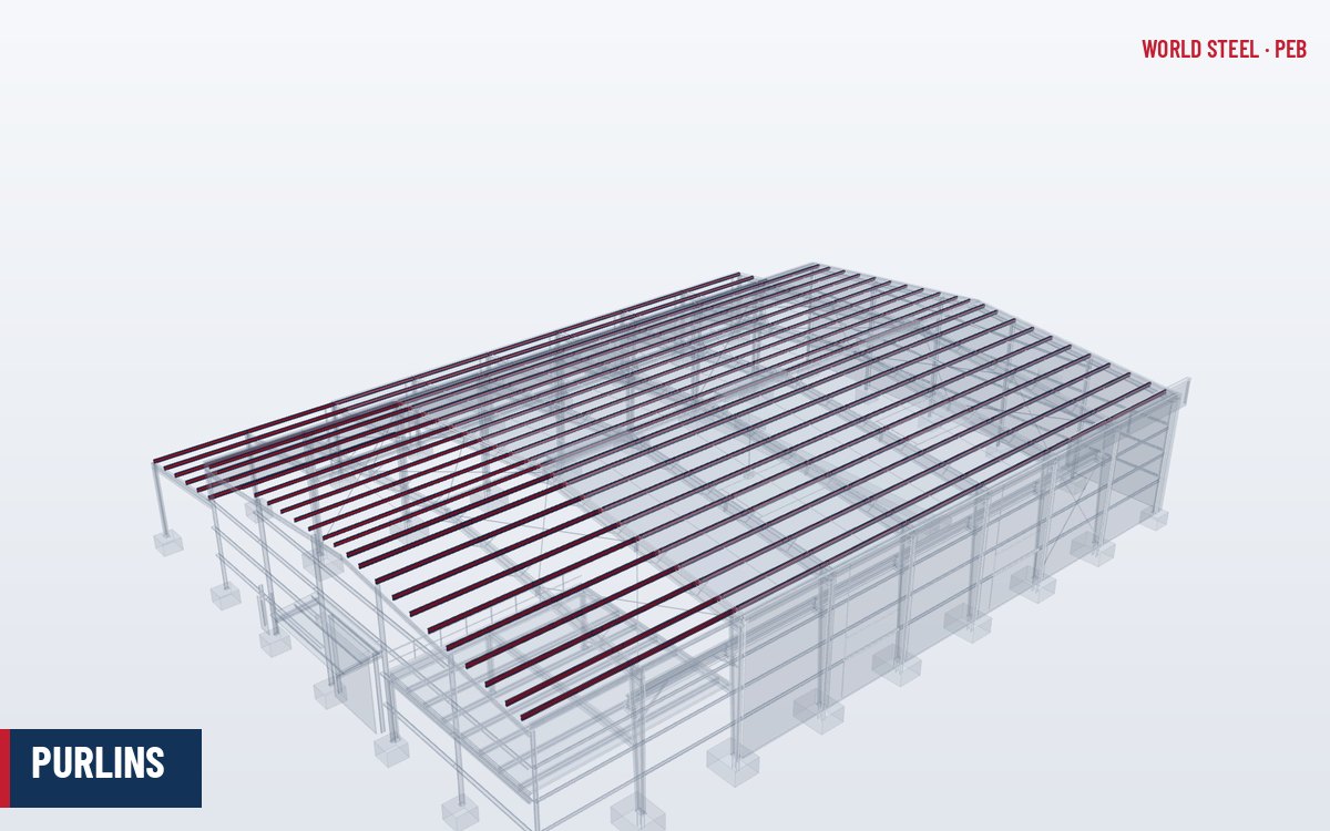
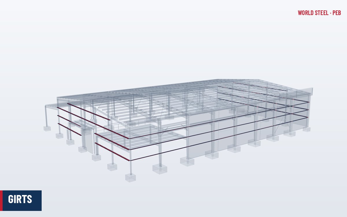
Braces are placed at purlin or girt positions where the design calls for restraint – often every second or third purlin near the knees and along the rafter, and at selected girts on columns. The positions are shown on the erection drawings, and each brace carries a mark number so that it can be matched to its frame line and purlin on site.
Design considerations
- Brace strength and stiffness: AISC 360-22 Appendix 6 sets required strength and stiffness for point bracing; EN 1993-1-1 and AS 4100:2020 have equivalent rules.
- Purlin capacity: the purlin and its lap must carry the brace force; deep frame members create larger brace forces.
- Brace angle: very shallow angles reduce effectiveness and increase force.
- Both-side bracing may be needed where purlins are lapped or where a single brace would twist the purlin.
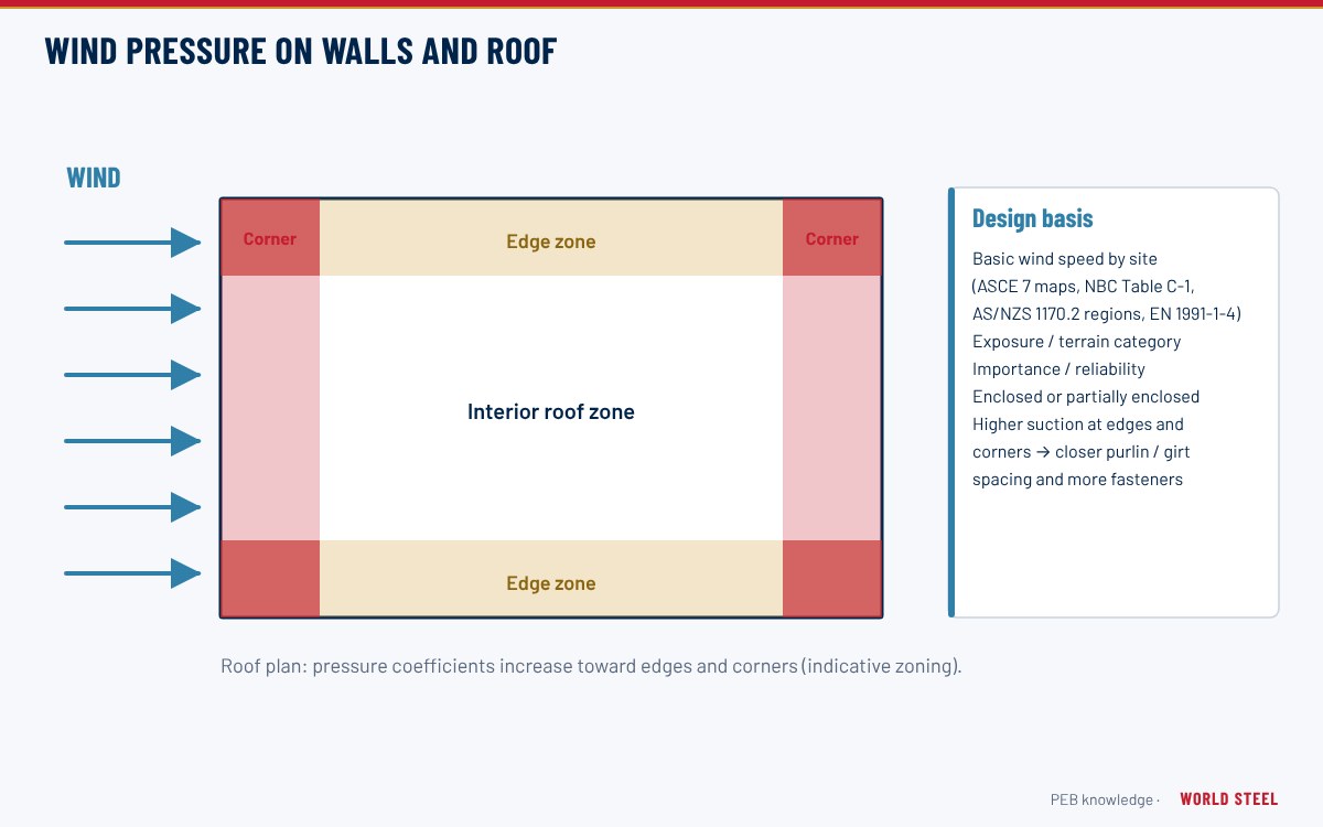
- Uplift: in high-wind regions the rafter inner flange is in compression for long lengths, so more braces are needed than for gravity alone.
The interaction between frame, purlins and braces is part of the frame optimisation: adding braces can reduce frame weight.
| Term or device | What it is | Where the term is used |
|---|---|---|
| Flange brace | Angle from purlin or girt web to the inner flange | US and general PEB practice |
| Fly brace | Same function; often a pair of angles or a cold-formed strap | Australia and New Zealand |
| Rafter or column stay | Same function, sometimes a tube or flat bar | UK and European practice |
| Torsional restraint via deep purlin connection | Stiff purlin-to-rafter connection that resists twist of the member | Considered in EN 1993-1-1 stable-length checks and advanced analysis |
| Web stiffener plus brace | Stiffener at the brace point to prevent local web distortion | Deep, slender webs near the haunch |
AS 4100:2020 classifies cross-section restraints as full (F), partial (P) or lateral (L); a flange brace to the critical flange combined with the purlin on the other flange typically gives a full or partial restraint, which sets the segment length used in the member check. Other codes reach the same result through brace stiffness and strength requirements.
Fabrication and installation
World Steel supplies flange braces cut, punched and marked by location, with matching holes or clips on the frame inner flange and on the purlins. On site, braces are installed after the purlins or girts are bolted and before temporary bracing is released. They should be bolted snug and the frame flange checked for straightness.
Common mistakes and quality checks
- Braces omitted because they are small and "look non-structural" – one of the most common causes of frame instability.
- Braces attached to the wrong purlin or wrong side.
- Braces removed later to install services, ducts or ceilings.
- Bolts missing at the purlin end.
Never remove or relocate flange braces without written approval from the building's engineer of record.
Normas por región
| Región | Norma | Alcance |
|---|---|---|
 United States |
AISC 360-22 App. 6 | Member stability bracing |
 Canada |
CSA S16-19 | Bracing requirements for members |
 Australia / NZ |
AS 4100:2020 | Restraint of members |
 Europe |
EN 1993-1-1 | Stability of members and bracing |
Preguntas frecuentes
Why does a PEB need flange braces?
The inner flange of rafters and columns is often in compression but not directly attached to purlins or girts. Flange braces stop it from buckling sideways.
Can flange braces be removed for services?
No, not without the engineer of record's approval. Removing them can significantly reduce frame capacity.
Where are flange braces located?
At purlin and girt positions identified by the frame design, usually concentrated near knees and along rafters subject to uplift.