 ENEnglish
 VITiếng Việt
 ZH中文
 KO한국어
 JA日本語
 FRFrançais
 ITItaliano
 PTPortuguês
 ESEspañol
 HEעברית
 ARالعربية

Definition and function
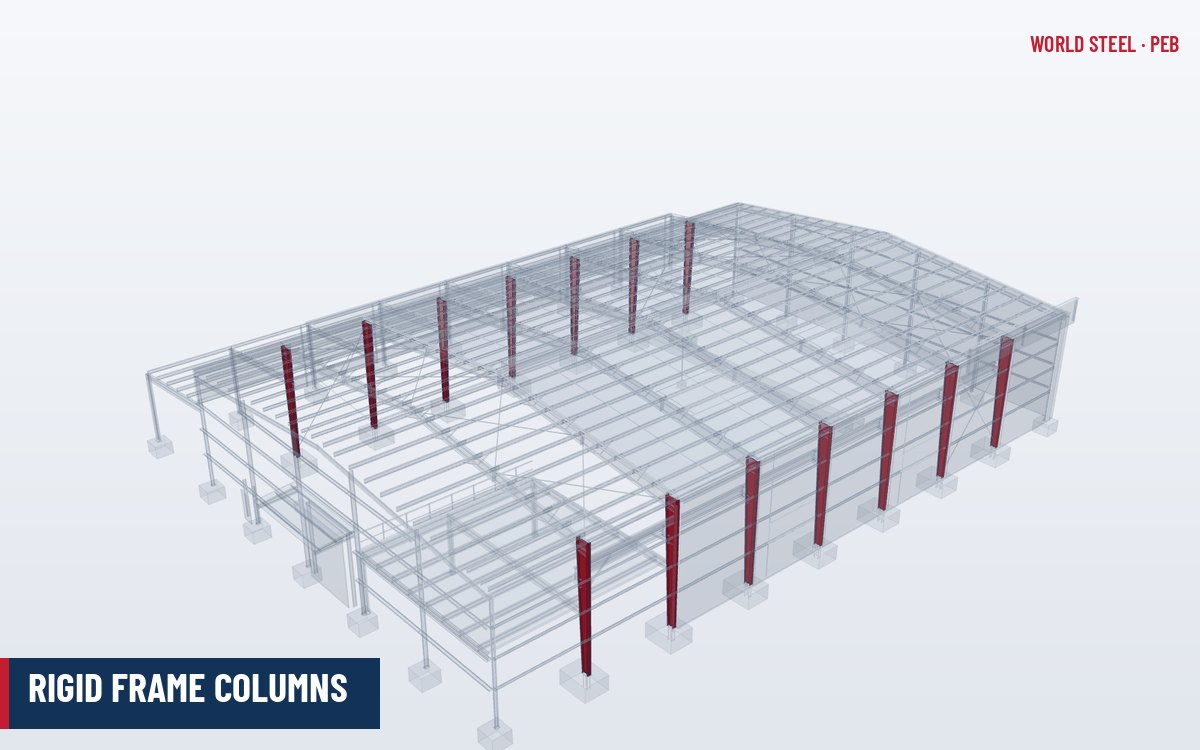
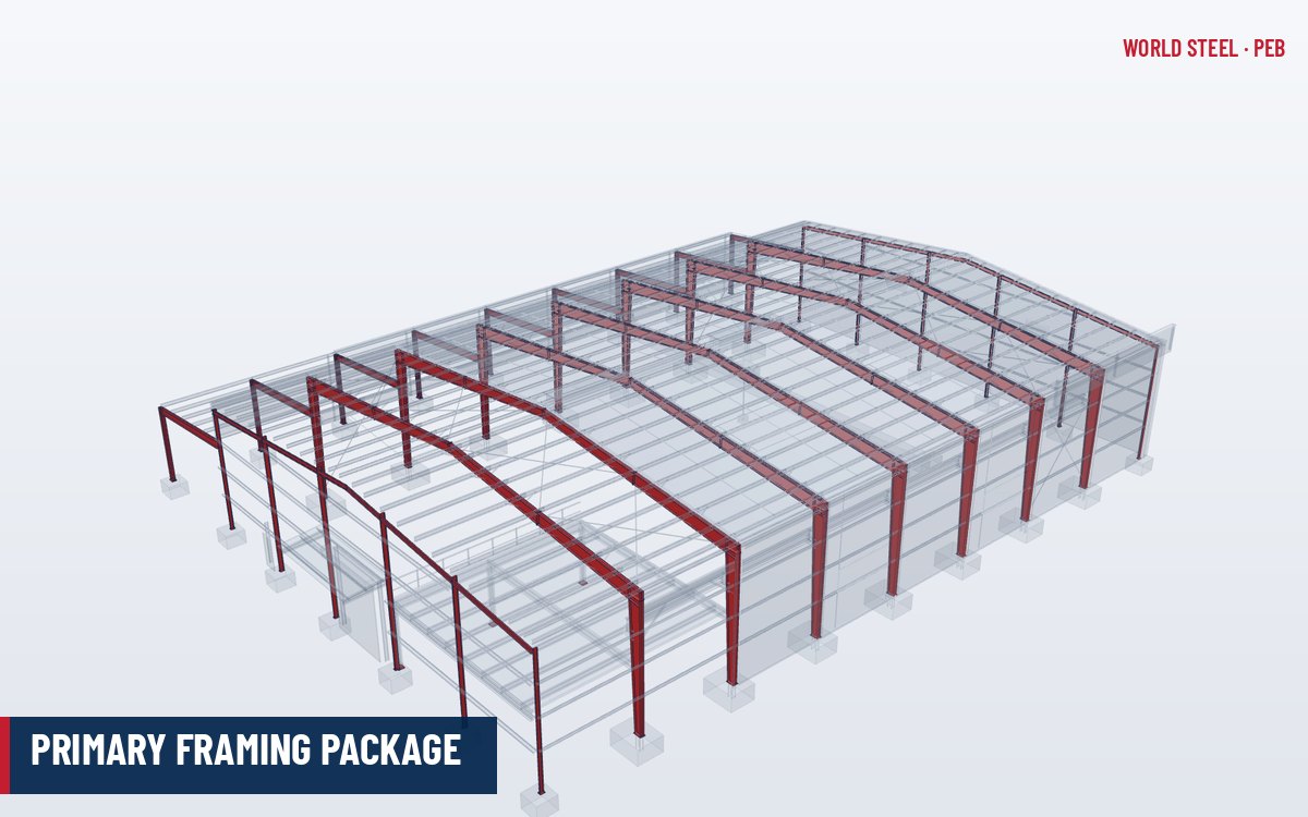
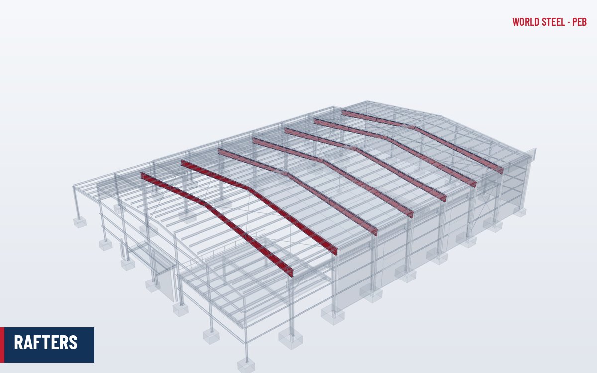
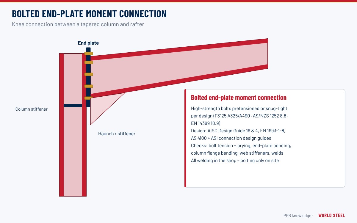
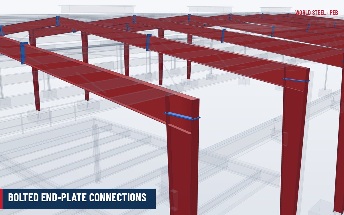
A bolted end-plate connection joins two members of the primary frame through steel plates welded to their ends and bolted together on site. In a pre-engineered building end plates are used at the knee (column to rafter), at the ridge (rafter to rafter) and at field splices within long rafters and columns. They are moment-resisting: they transfer bending moment, shear and axial force, so the frame behaves as a continuous portal.
The principal advantage is that all welding is done under controlled shop conditions and the site work is reduced to bolting. This is a key reason PEB frames erect quickly and consistently.
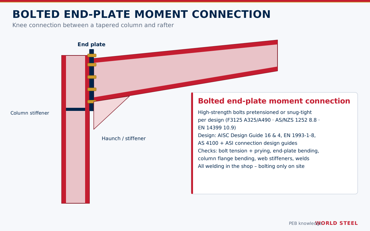
Connection types and where they sit in the load path
The connection carries the frame moment across the joint: the tension flange pulls on the bolts nearest to it, while the compression flange bears through the plates. The rafter delivers its moment and shear through the knee into the column.
| Type | Description | Typical use |
|---|---|---|
| Flush end plate | Plate within beam depth; bolts inside flanges | Ridge and splices with moderate moment |
| Extended end plate | Plate extends beyond tension flange with outer bolt row | Knees and highly loaded splices |
| Stiffened extended | Extension stiffened by a rib plate | High moments, seismic frames |
| Multiple-row | Two or more bolt rows at each flange | Deep haunches with large moments |
| Joint | Typical arrangement | Comment |
|---|---|---|
| Knee – vertical end plate | Rafter end plate bolted to the column flange or column cap end plate | Most common; column top often stiffened |
| Knee – horizontal end plate | Rafter seated on a horizontal plate on top of a deep column | Used where the haunch is part of the column piece |
| Ridge | Two rafter end plates bolted at the apex | Moment usually lower than at the knee; flush plates common |
| Rafter field splice | Flush or extended plates at transport breaks | Located where moment is low and within shipping length |
| Column splice | End plates or bolted flange cover plates | Tall columns, stepped crane columns |
| Interior column cap | Rafter bottom flange bolted to a column cap plate | Bearing and shear connection in multi-span frames |
Typical plate, bolt and weld sizes
| Item | Typical range |
|---|---|
| End-plate thickness | 12–40 mm |
| Bolt diameter | M16–M30 (5/8"–1-1/4") |
| Bolt grade | ASTM F3125 A325/A490; property class 8.8 or 10.9 |
| Flange-to-plate weld | Fillet or complete-joint-penetration per design |
| Web-to-plate weld | Fillet welds, both sides |
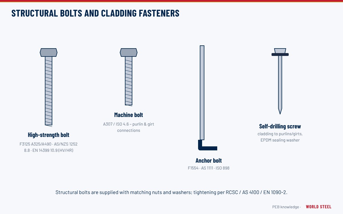
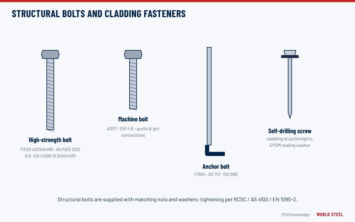
For bolt and fastener material see structural bolts and cladding fasteners. End plates are usually cut from 345–355 MPa plate; through-thickness properties may need attention for thick plates in highly loaded joints.
Design considerations
- US: AISC Design Guide 39 (End-Plate Moment Connections, 2023) consolidates and replaces the earlier Design Guides 4 and 16; AISC 358 covers prequalified end-plate connections for seismic moment frames.
- Europe: EN 1993-1-8 component method, including T-stub analysis and rotational stiffness classification.
- Australia / NZ and Canada: AS 4100:2020 and CSA S16-19 member and connection provisions, with industry design guides.
- Prying action on thin plates increases bolt tension – thicker plates or stiffeners reduce it.
- Panel zone of the column at the knee may need diagonal or horizontal stiffeners.
- Bolt pretension: the design states whether bolts are snug-tight or pretensioned. Moment end plates are typically pretensioned under the RCSC Specification.
Connection design is covered in more detail under connection design.
Fabrication and installation
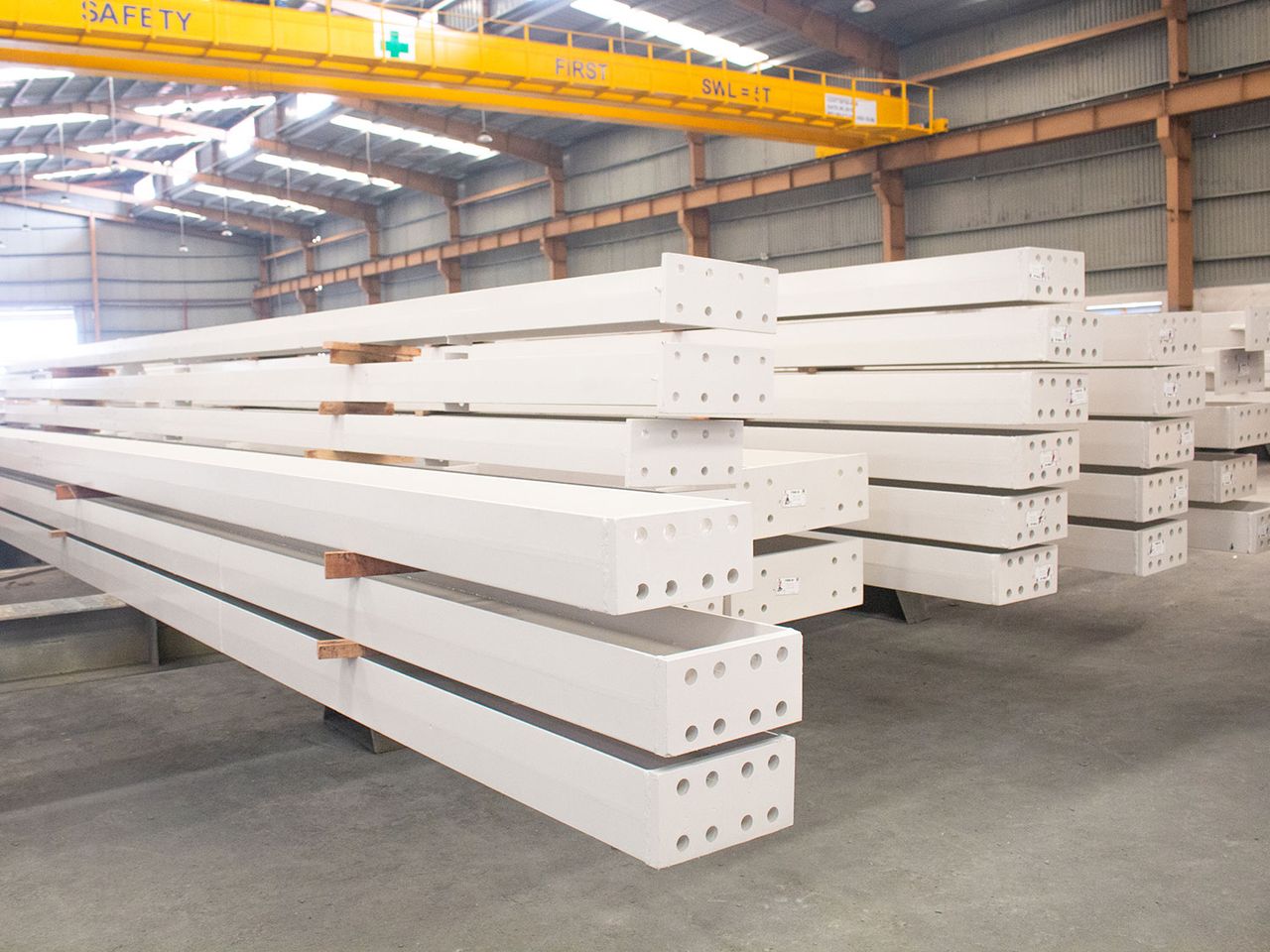
World Steel cuts and drills end plates on CNC lines, welds them square to the member axis (or at the roof slope for knees and ridges) and checks flatness after welding, because distortion causes gaps on site. Faying surfaces are masked or coated as specified when slip-critical joints are required.
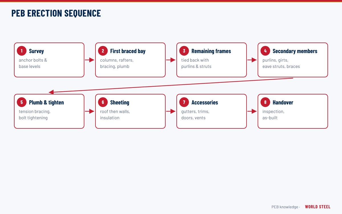
- Bring plates together and insert all bolts with washers as detailed.
- Snug-tighten bolts in a pattern from the centre outward until the plates are in firm contact.
- Pretension by turn-of-nut, calibrated wrench, direct tension indicators or twist-off bolts where required.
- Mark tightened bolts and record inspection.
Common mistakes and quality checks
- Gaps between plates from weld distortion – check plate flatness in the shop.
- Wrong bolt grade or length; mixing grades between connections.
- Galvanised or lubricated bolts reused after pretensioning.
- Paint on faying surfaces of slip-critical joints not matching the specified slip class.
- Bolts left snug-tight when pretension was required – verify with inspection records.
Normas por región
| Región | Norma | Alcance |
|---|---|---|
 United States |
AISC 360-22 / AISC DG 39 / RCSC | Connection design, end-plate design guide and high-strength bolt specification |
 Canada |
CSA S16-19 | Bolted connections and pretensioning |
 Australia / NZ |
AS 4100:2020 / AS/NZS 5131 | Connection design and bolt installation |
 Europe |
EN 1993-1-8 / EN 1090-2 | Design of joints and execution of bolting |
| International | EN 14399 / ASTM F3125 | Preloadable and high-strength structural bolts |
Preguntas frecuentes
Do end-plate connections need site welding?
No. All welding of end plates is done in the factory; site work is limited to bolting, which speeds erection and improves consistency.
Must end-plate bolts be pretensioned?
Moment end-plate connections are generally pretensioned. The design drawings state the joint type, and the installer must follow the specified method and inspection.
What causes gaps between end plates?
Mainly weld distortion during fabrication or misaligned members. Plates should be checked for flatness in the shop and gaps limited to the specified tolerance before pretensioning.