 ENEnglish
 VITiếng Việt
 ZH中文
 KO한국어
 JA日本語
 FRFrançais
 ITItaliano
 PTPortuguês
 ESEspañol
 HEעברית
 ARالعربية

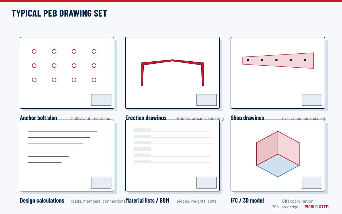
The deliverables chain
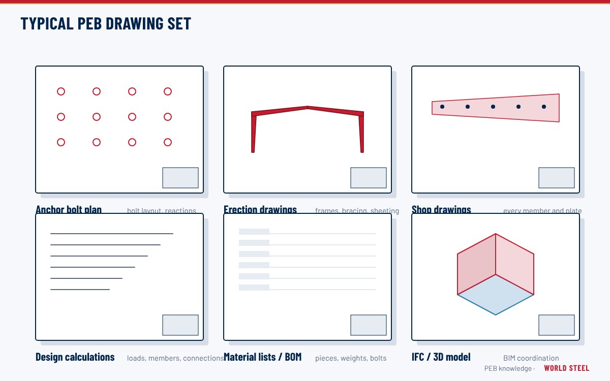
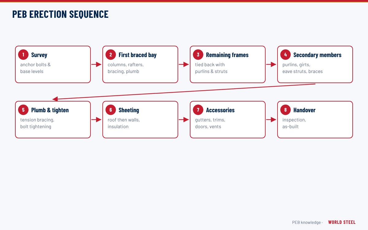
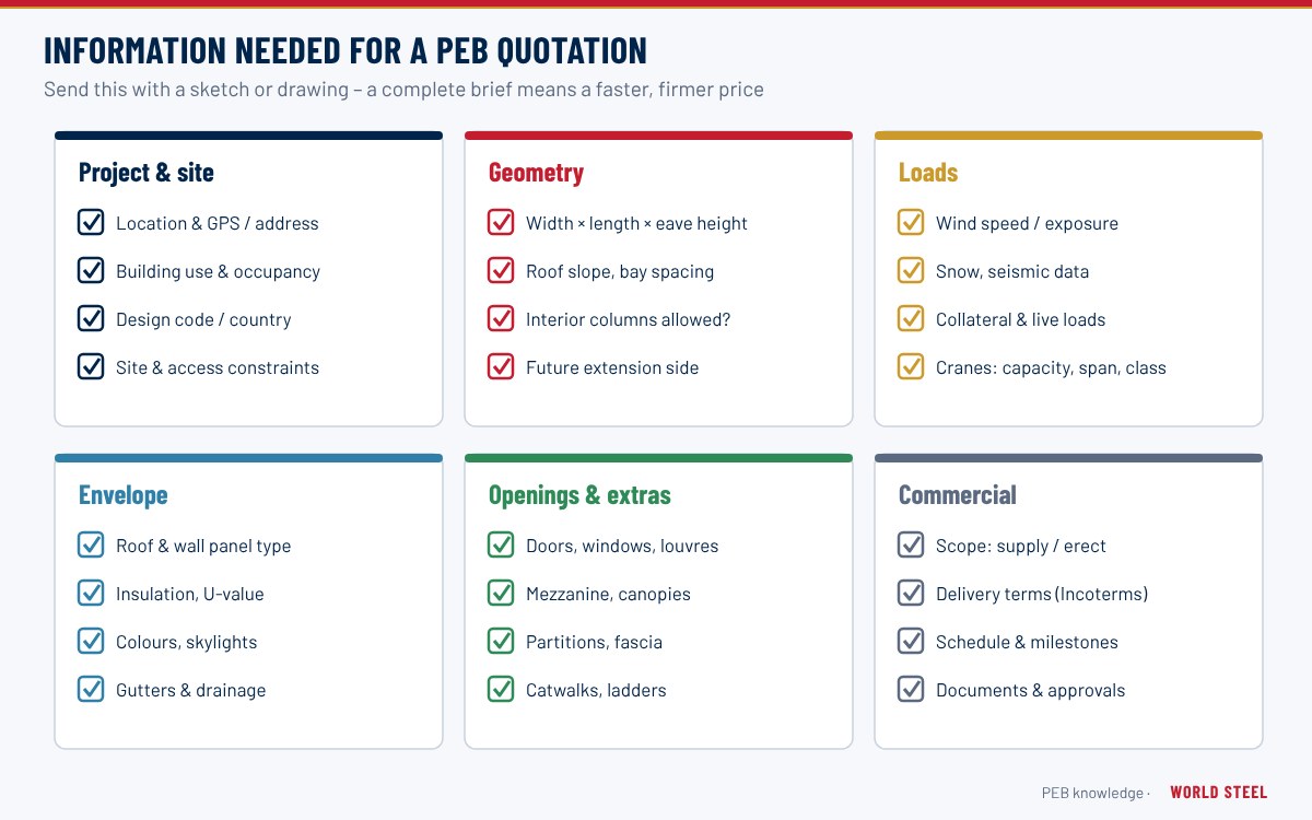
A pre-engineered building moves from enquiry to site through a defined sequence of design deliverables. Each one serves a different reader – owner, architect, engineer of record, building authority, foundation contractor, fabricator or erector – and each has a clear approval step. Understanding the set helps buyers review submissions quickly and avoid delays. The typical sequence is:
- Design criteria and quotation drawings
- Approval (general arrangement) drawings
- Anchor bolt plan and reactions
- Design calculations (and, where required, sealed submissions)
- Erection drawings
- Shop (fabrication) drawings and CNC data
- 3D model / IFC and as-built records
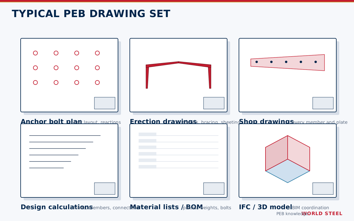
What each deliverable contains
| Deliverable | Contents | Used by |
|---|---|---|
| Approval drawings | Plans, elevations, cross-sections, frame lines, openings, accessories, design loads and codes | Owner and architect – to confirm scope and geometry |
| Anchor bolt plan | Anchor bolt locations, diameters, projections, base plate sizes, column reactions by load case | Foundation designer and civil contractor |
| Design calculations | Design criteria, loads and combinations, frame analysis, member, connection, purlin, girt and bracing checks, deflections | Engineer of record, checking engineer, authority |
| Erection drawings | Member marks, frame cross-sections, roof and wall framing plans, bracing, bolt schedules, sheeting and trim layouts, details | Erector and site supervisor |
| Shop drawings | Individual part drawings: plate sizes, holes, welds, coatings, piece marks | Fabrication shop and QC |
| IFC / 3D model | Openly exchangeable BIM model of the steel structure for coordination and clash checks | Design team, MEP coordinators, owner |
| Packing lists and bills of material | Piece lists by container or bundle | Logistics and site receiving |
Anchor bolt plan first
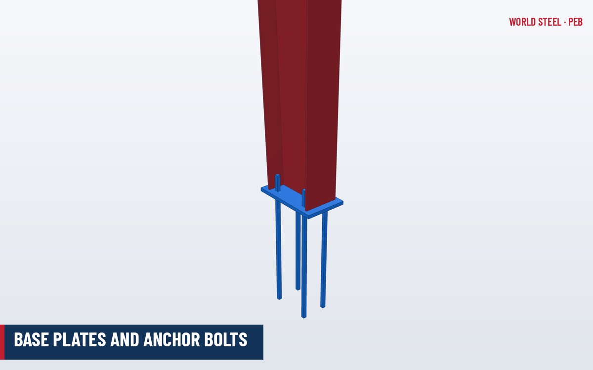
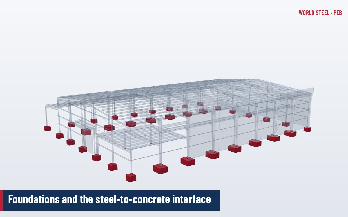
Foundations are usually built by a local contractor while the steel is in fabrication, so the anchor bolt plan and reactions are issued first, typically immediately after approval drawings are signed. Reactions are given unfactored by load type (dead, collateral, live, snow, wind, seismic, crane) so the foundation designer can apply local combinations. Anchor bolt projections, grout thickness and tolerances must be respected; see base plates and anchor bolts and foundations interface.
Calculations, approvals and local requirements
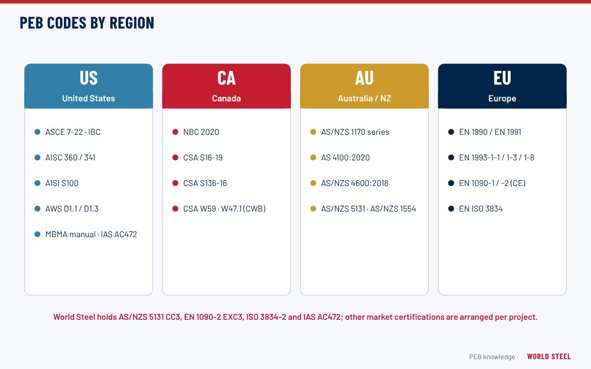
- United States and Canada: building permits typically require drawings and calculations sealed by an engineer licensed in the state or province; Canadian projects also need a letter of assurance or similar from the designer.
- Australia and New Zealand: design certification by a chartered or registered engineer (e.g. CPEng / RPEQ in Queensland) under the National Construction Code or NZ Building Code.
- Europe: design to Eurocodes with National Annexes; CE marking under EN 1090-1 requires a factory production control route to be arranged per project.
- Most markets require that the design criteria – codes, loads, deflection limits, materials – be stated on the general notes of the drawings.
Late changes to openings, cranes, mezzanines or loads after approval drawings affect calculations, anchor bolts and fabrication. Freeze scope at the approval stage wherever possible.
Design certification and what the erection set contains
Many authorities and owners ask the PEB supplier for a formal statement that the building was designed for the specified criteria. In North American practice this is a letter of design certification (or letter of assurance in some Canadian provinces) signed by the supplier's engineer, listing the code edition, risk category, roof live, snow, collateral, wind and seismic parameters, crane and mezzanine loads, and the deflection criteria used. In Australia and New Zealand an equivalent design certificate is issued by the registered engineer, and in Europe the design basis is recorded in the declaration documentation for the steel components. The certificate covers the steel package only; foundations, slab and non-supplied items remain with the engineer of record.
| Sheet | Shows |
|---|---|
| General notes and design criteria | Codes, loads, materials, coatings, bolt grades and tightening, deflection criteria |
| Anchor bolt plan and details | Bolt layout, projections, base plate orientation, reactions |
| Cross-sections | Each frame type with member marks, splice and connection details |
| Roof framing plan | Purlin layout and laps, roof bracing, sag rods, skylights, ventilators |
| Sidewall and endwall framing elevations | Girts, wall bracing, framed openings, endwall posts |
| Sheeting and trim layouts | Panel runs, laps, fastener patterns, trims, gutters and downspouts |
| Standard details and bolt schedule | Flange braces, clips, flashings, bolt sizes and quantities per connection |
Each issue carries a revision mark and date; superseded sheets should be withdrawn from site so that erection always follows the current revision.
Erection, shop drawings and IFC at WSC
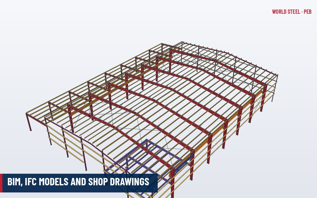
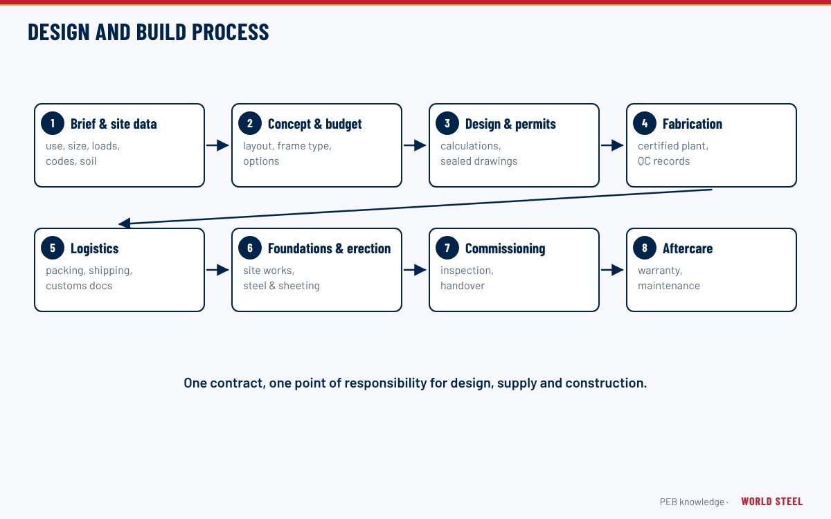
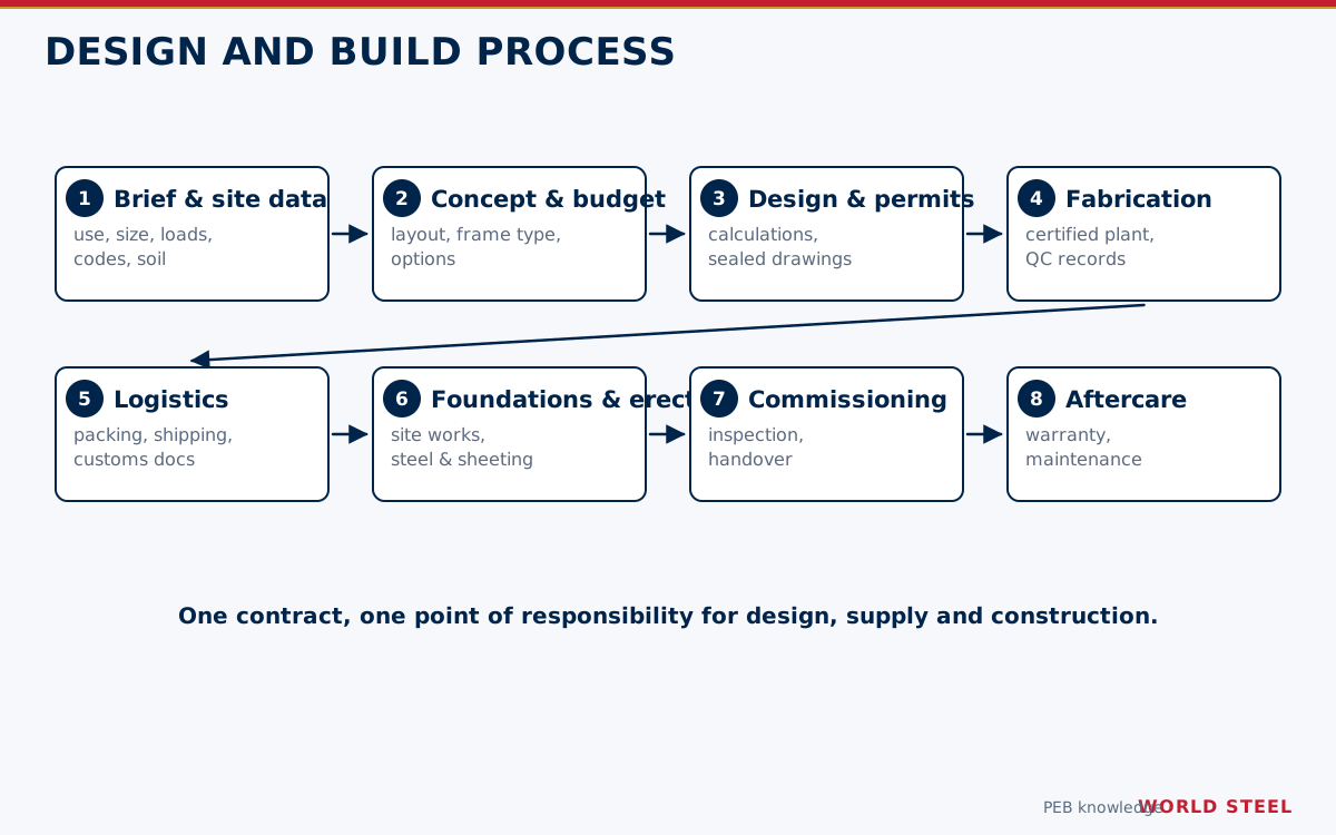
World Steel produces the full deliverable set in-house: approval drawings, anchor bolt plans, calculations, erection and shop drawings, CNC data for cutting and drilling lines, and IFC models for coordination. The IFC model allows clients and consultants to check clashes with services and view the structure in 3D. Learn more in BIM, IFC and shop drawings, the design-and-build process, and WSC's design service.
Norme per regione
| Regione | Norma | Ambito |
|---|---|---|
 United States |
MBMA 2018 | Metal Building Systems Manual – common industry practices |
| United States |
AISC 303-22 | Code of Standard Practice for Steel Buildings and Bridges |
 Canada |
CISC Code of Standard Practice | Structural steel documents and responsibilities |
 Australia / NZ |
AS/NZS 5131:2016 | Fabrication and erection – documentation requirements |
 Europe |
EN 1090-2 | Execution of steel structures – execution specification |
| International | ISO 16739-1 | Industry Foundation Classes (IFC) for data sharing |
Domande frequenti
Why is the anchor bolt plan issued before other drawings?
Foundations must be built while steel is fabricated. Issuing anchor bolt layouts and reactions early lets the civil contractor start without waiting for the full drawing set.
Are reactions on the anchor bolt plan factored?
They are normally given unfactored by load type, so the foundation engineer can apply the local code's load combinations.
What is an IFC model used for?
IFC is an open BIM format. It lets architects, MEP engineers and owners view and coordinate the steel model in their own software, check clashes and keep a digital record.
What is a letter of design certification?
It is a signed statement from the PEB supplier's engineer that the steel building has been designed for the listed code, loads and criteria. Authorities and owners often require it with the permit or as-built documents; it does not cover foundations or items not supplied by the PEB manufacturer.