 ENEnglish
 VITiếng Việt
 ZH中文
 KO한국어
 JA日本語
 FRFrançais
 ITItaliano
 PTPortuguês
 ESEspañol
 HEעברית
 ARالعربية

What the interface is and who is responsible
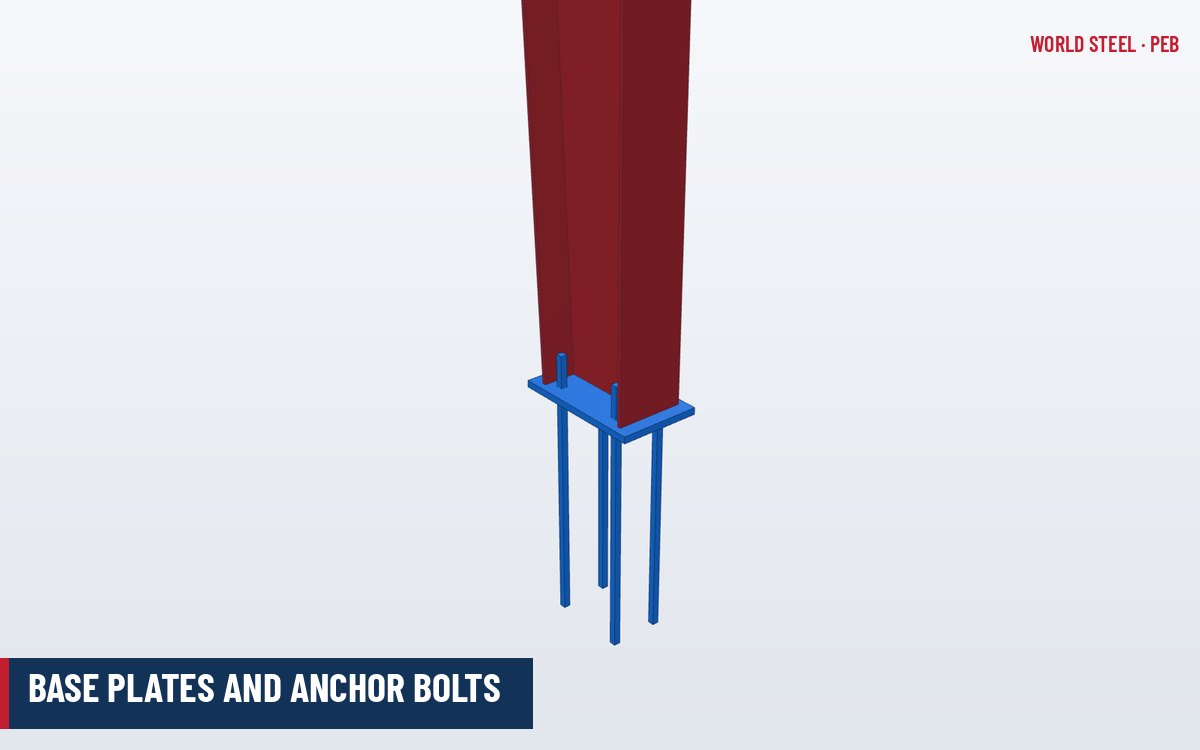
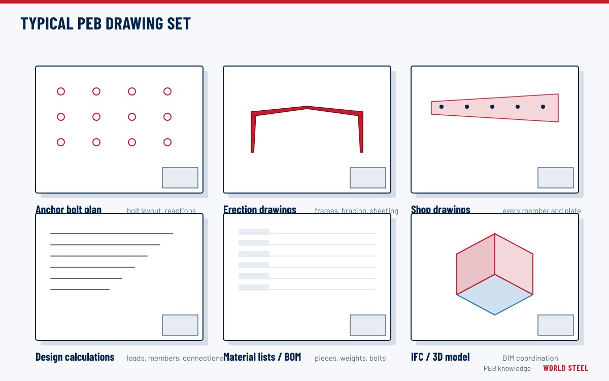
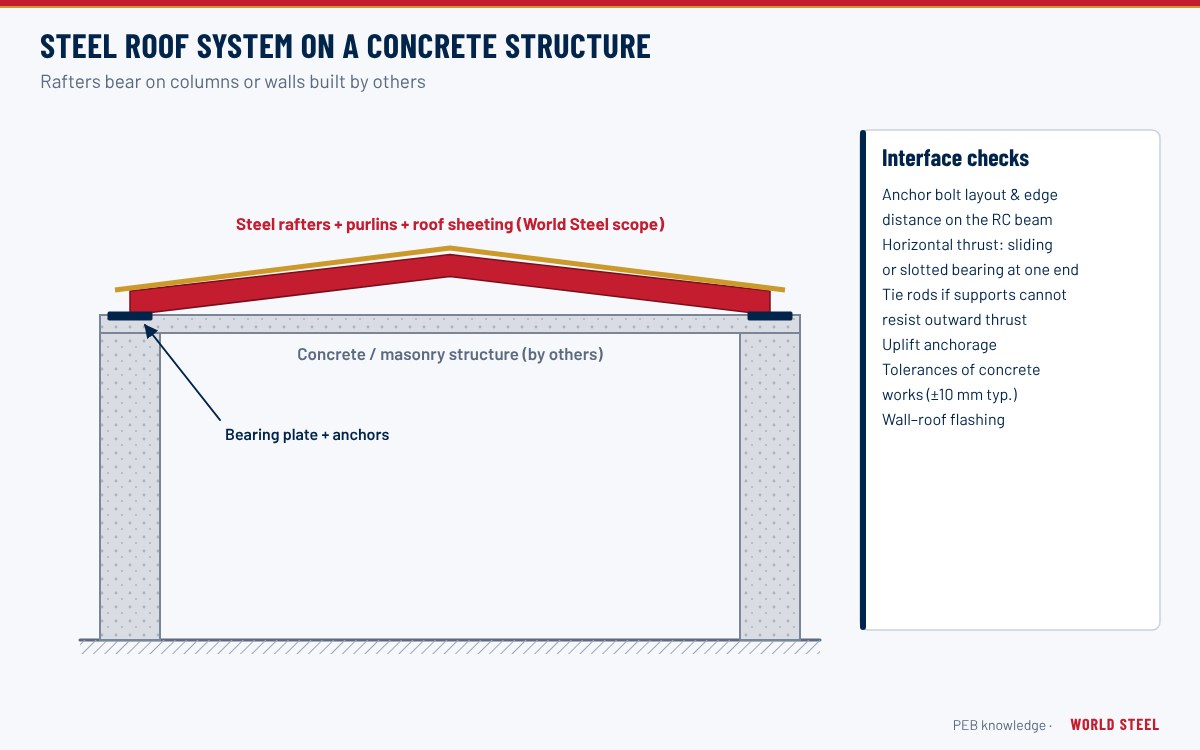
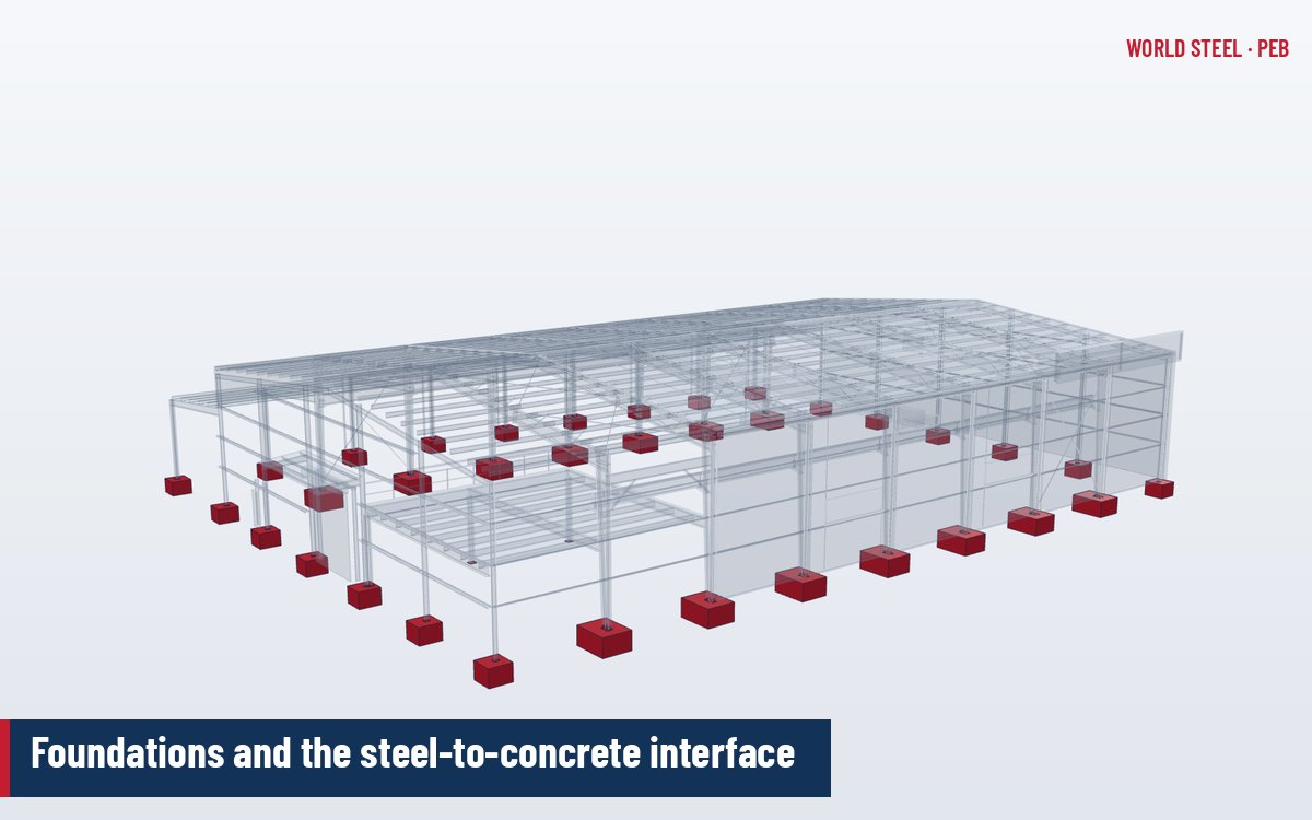
In a pre-engineered building the steel supplier designs the superstructure and the foundations are normally designed and built by others – the owner's civil engineer and contractor. The interface between them is the base plate and anchor bolt connection, and it is defined by three documents from the PEB designer:
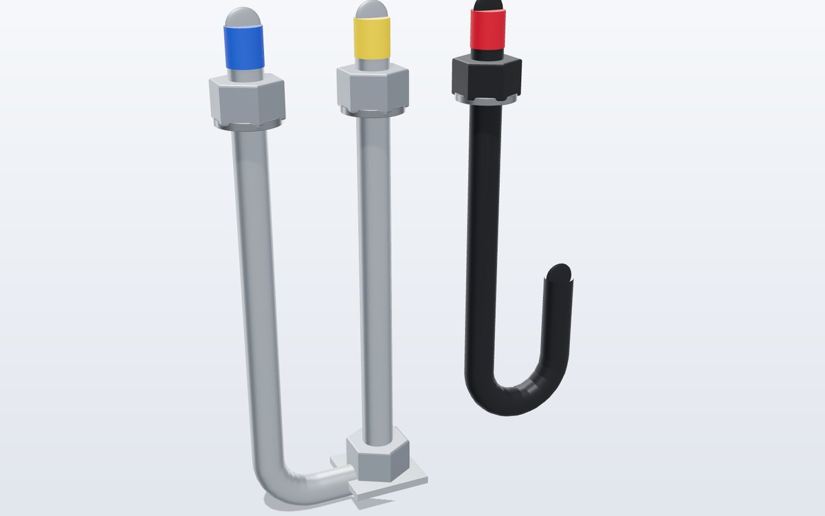
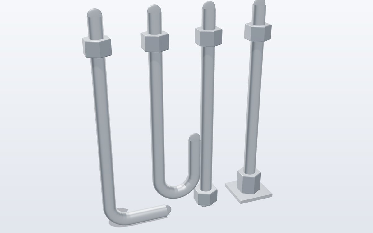
- Anchor bolt plan: grid lines, bolt positions, projections, diameters and base elevations for every column.
- Reaction table: unfactored column reactions for each load case (dead, collateral, live, snow, wind, seismic, crane) so the foundation engineer can form the local load combinations.
- Embedment and detail notes: anchor type, plate washers, shear lugs, grout and any slab-tie requirements.
A clear interface is one of the most important coordination items in a PEB project, because foundations are poured long before the steel arrives.
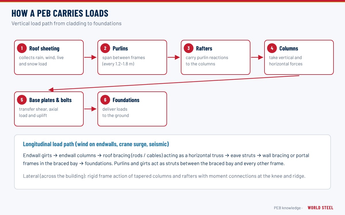
Foundations in the load path
The footing is the last element of the load path. It receives vertical compression and uplift, horizontal thrust from the portal frames, longitudinal forces from braced bays and, where bases are fixed, moment.
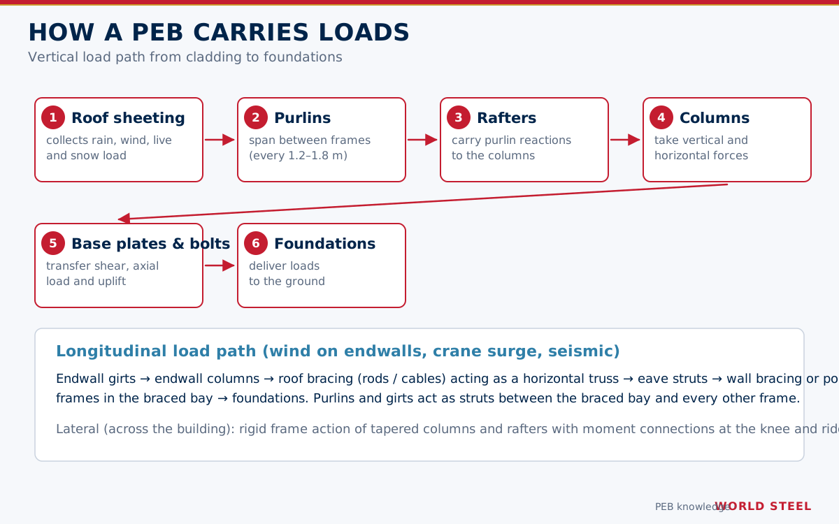
Frame thrust deserves special attention: gable portal frames push their bases outward under gravity load and may pull inward under uplift. It can be resisted by the footing in passive soil pressure and friction, by tie beams between opposite footings, by hairpin bars anchored into the slab, or by piles designed for lateral load.
Typical foundation types
| Type | When used | Thrust resistance |
|---|---|---|
| Isolated pad footing with pedestal | Good bearing soil, pinned bases | Soil friction / passive pressure, tie beams or hairpins |
| Pad footing with tie beams | Moderate soils, large thrust | Ties across the span or along grid lines |
| Strip footing | Closely spaced endwall columns, perimeter walls | Continuous footing |
| Pile cap on piles | Soft soils, reclaimed land | Raked piles or lateral pile capacity |
| Combined footing | Double columns at expansion joints, closely spaced frame and endwall columns | Single footing for both columns |
| Raft (mat) foundation | Very weak soils or heavy floor loads over the whole area | Raft ties all columns |
| Thickened slab edge | Small light buildings | Slab acts as tie |
Perimeter upstand or block walls (dado walls) are common under the wall sheeting; their top level and setback must be coordinated with the base trim and girt layout of the wall sheeting.
Design considerations
- Use the reactions with the local concrete code (ACI 318, CSA A23.3, AS 3600, EN 1992-1-1) and load combinations for the site.
- Check uplift: light steel buildings in high-wind areas often need heavy footings to resist net uplift.
- Anchorage design for breakout and pull-out: ACI 318 Chapter 17, CSA A23.3 Annex D, AS 5216 or EN 1992-4.
- Pedestal top level allows for grout (typically 25–50 mm) and finished floor level.
- Future expansion – provide footings and anchors for expandable endwalls where planned.
- Crane buildings – fixed bases and crane loads significantly increase footing size; see crane buildings.
Pinned versus fixed bases and the slab-on-grade
| Aspect | Pinned base | Fixed base |
|---|---|---|
| Reactions | Vertical load, uplift, horizontal shear | Same, plus significant overturning moment |
| Footing size | Smaller; often governed by uplift | Larger and deeper to resist moment and limit rotation |
| Anchor bolts | 2–4 bolts near the column web | 4–8+ bolts outside the flanges, deeper embedment |
| Sensitivity to soil | Low | High – footing rotation reduces the assumed fixity |
| Typical use | Most PEB frames | Cranes, tall eaves, tight drift limits |
The slab-on-grade is normally poured after the steel is erected and the roof is on, so that it is protected from weather. Its thickness and reinforcement are set by forklift wheel loads, rack post loads and the subgrade – industrial slabs of roughly 150–250 mm are common. At the columns:
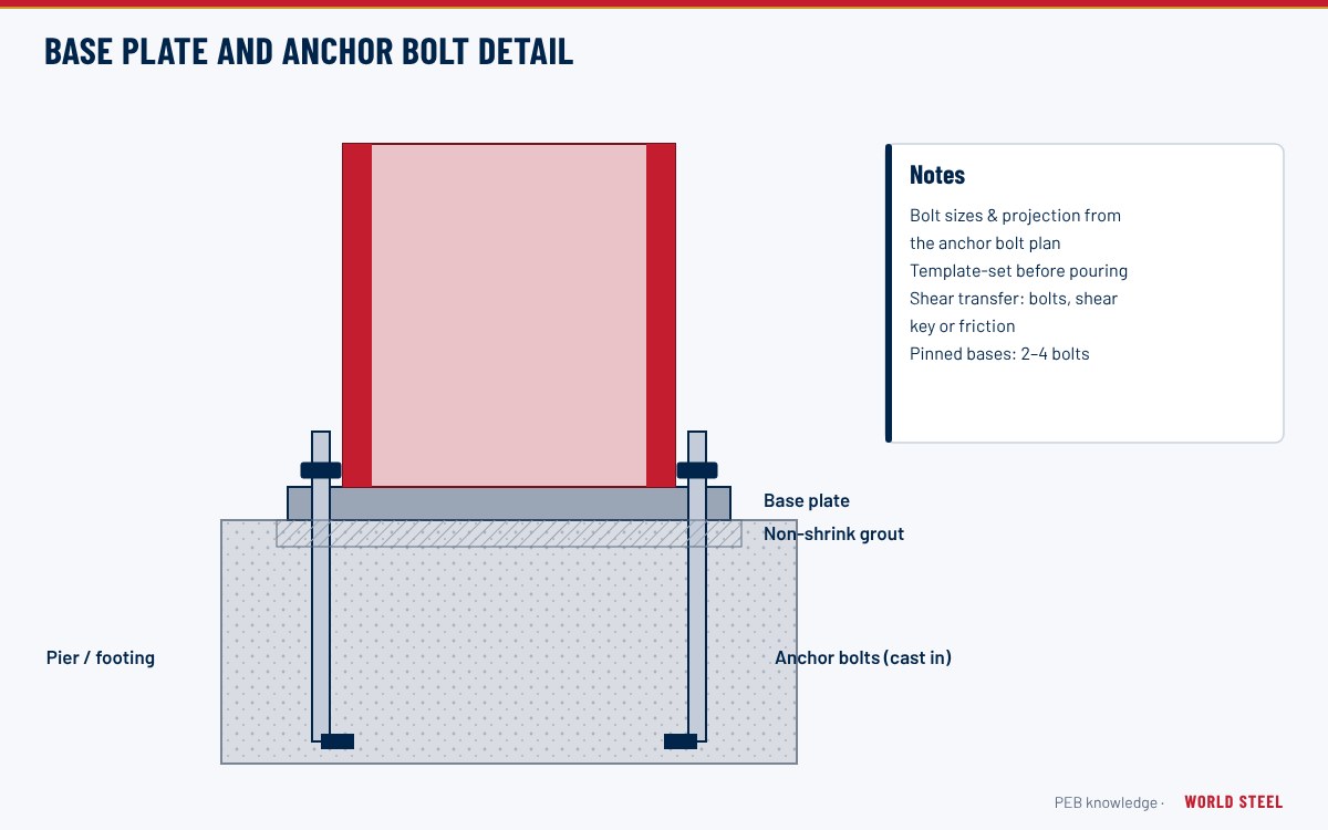
- The base plate is usually set below finished floor level on a pedestal, then encased or boxed out; isolation joints around columns (circular or diamond-shaped blockouts) prevent restraint cracking.
- Where the slab acts as a tie for frame thrust, hairpin bars around the anchor bolts are lapped into the slab reinforcement, and saw-cut joints must not cut through the tie path.
- At door openings the slab edge is rebated or thickened to suit door tracks, and the base trim and girt level are coordinated with the slab edge and any dado wall.
- Under-slab services, valley-gutter downpipes and crane rail foundations must be set out before the pour.
Setting anchors, tolerances and grouting
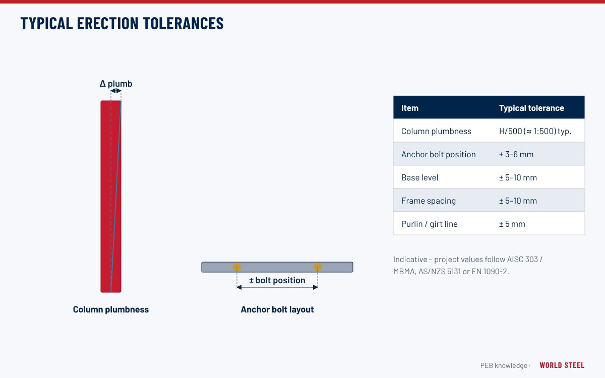
Anchors should be set with rigid templates, ideally the steel templates supplied with the anchor bolt package, and surveyed after the pour. Typical limits in the AISC Code of Standard Practice include 1/8 in between rods within a group and 1/4 in between adjacent groups; AS/NZS 5131 and EN 1090-2 give comparable limits for anchor and base positions. See erection tolerances.
- Fix templates to formwork and check grid and level before pouring.
- Protect threads with sleeves or tape.
- Survey anchors and pedestal levels after curing and report deviations before the steel ships.
- After erection and alignment, fill under base plates with non-shrink grout.
Common mistakes and quality checks
- Foundations designed before the final anchor bolt plan is issued – always design from the "approved for construction" drawing revision.
- Thrust ignored or tie beams omitted.
- Anchors displaced during concreting by vibrators.
- Slab joints conflicting with anchor groups or hairpins.
- Endwall and wind-column anchors missed on the civil drawings.
World Steel issues the anchor bolt plan and reaction tables early, and its engineering team coordinates with the foundation designer when the client requests it.
Norme per regione
| Regione | Norma | Ambito |
|---|---|---|
 United States |
ACI 318 / AISC COSP (AISC 303) | Concrete design, anchoring and anchor rod tolerances |
 Canada |
CSA A23.3 | Design of concrete structures including anchorage (Annex D) |
 Australia / NZ |
AS 3600 / AS 5216 / AS/NZS 5131 | Concrete structures, fastenings and steelwork tolerances |
 Europe |
EN 1992-1-1 / EN 1992-4 / EN 1090-2 | Concrete, fastenings and execution tolerances |
Domande frequenti
Does the PEB supplier design the foundations?
Usually not. The supplier provides reactions and the anchor bolt plan; the foundation is designed by a local engineer familiar with the soil and concrete code. Design-and-build contracts can include it.
What is frame thrust?
It is the horizontal reaction at the base of a portal frame caused by gravity and wind loads. It must be resisted by the footing, tie beams, hairpins or piles.
What happens if anchor bolts are out of tolerance?
The engineer must approve a fix, such as slotting or re-drilling the base plate, adding plate washers or installing post-installed anchors. Surveying anchors before shipment avoids most problems.
Can the floor slab resist the horizontal thrust of the frames?
Yes, if it is designed for it. Hairpin bars around the anchor bolts are lapped into the slab reinforcement so the slab acts as a tie between opposite columns. Slab joints, openings and pits must then be detailed so they do not interrupt the tie path; otherwise tie beams or larger footings are used.