 ENEnglish
 VITiếng Việt
 ZH中文
 KO한국어
 JA日本語
 FRFrançais
 ITItaliano
 PTPortuguês
 ESEspañol
 HEעברית
 ARالعربية

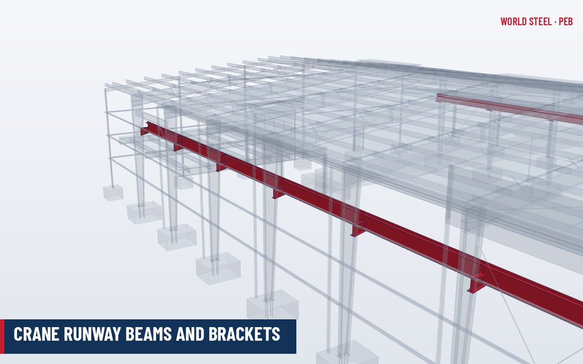
What a crane runway system is
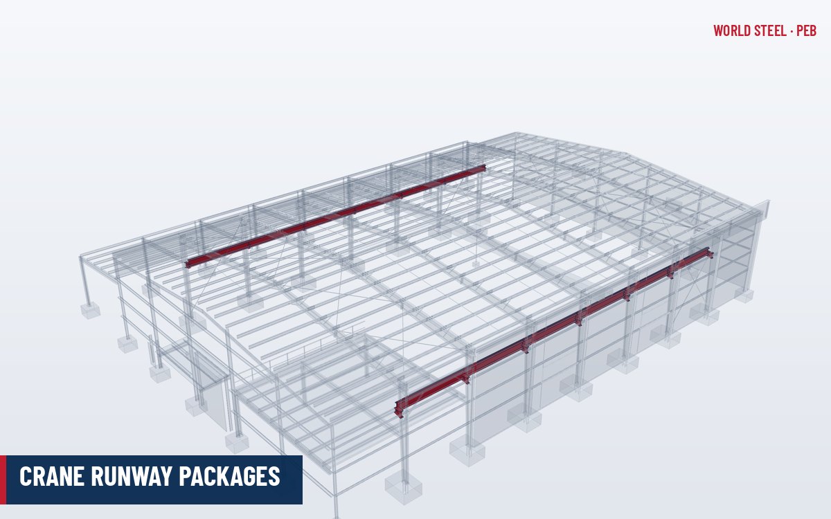
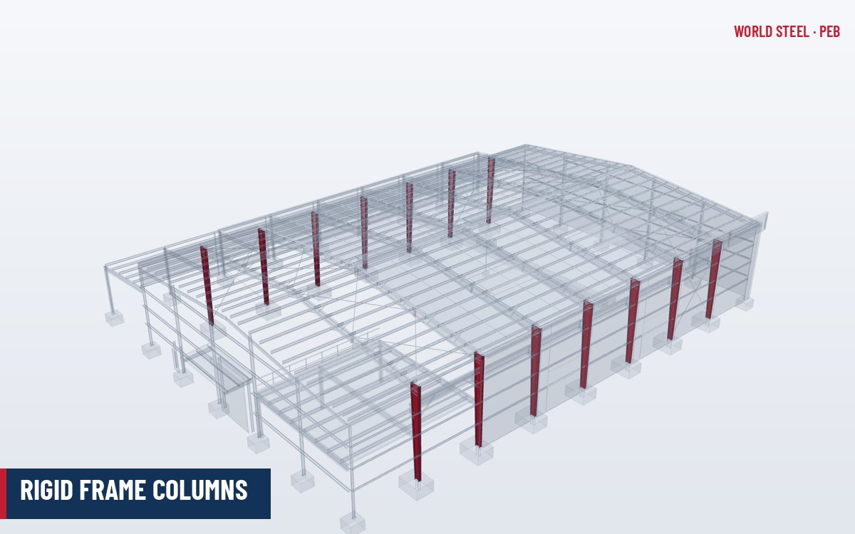
A crane runway is the pair of longitudinal beams, with rails, on which an overhead travelling crane moves along the building. In a pre-engineered building the runway beams normally sit on crane brackets welded or bolted to the rigid frame columns, or on separate crane columns or stepped columns for heavier cranes. The runway carries vertical wheel loads, lateral (side-thrust) forces from trolley movement, and longitudinal forces from crane acceleration and braking into the frames and the longitudinal bracing. Because these loads are repeated many thousands of times, runway design is governed by fatigue and serviceability as much as by strength. See crane buildings for the whole-building concept.
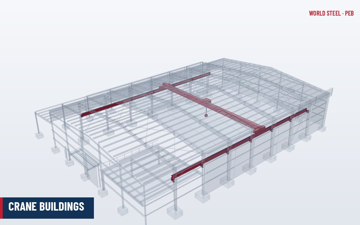
Crane types and how they load the building
The type of crane decides where the loads enter the structure and which members must be designed for them. Clarify the crane type with the owner and the crane supplier before the frames are designed.
| Crane type | How it is supported | Typical PEB application | Structural implications |
|---|---|---|---|
| Top-running bridge crane (single or double girder) | End trucks run on rails on top of runway beams | Workshops, steel stockyards, fabrication halls; light to heavy capacities | Runway beams on column brackets or crane columns; frame drift and fatigue govern |
| Underhung (under-running) bridge crane | End trucks run on the bottom flange of runway beams hung from the rafters | Light assembly and maintenance halls, usually a few tonnes | Loads hang from rafters or purlin-level beams; local flange bending and hanger fatigue must be checked |
| Monorail | Hoist trolley runs on the bottom flange of a single beam | Loading bays, process lines, pump houses | Beam hung from rafters or brackets; flange bending and end stops; longitudinal bracing of the beam |
| Jib crane (wall- or column-mounted) | Rotating boom on a building column | Workstations along a wall | Large local moment and torsion in the supporting column; often a dedicated column |
| Pillar (free-standing) jib crane | Own column on its own foundation | Workstations away from walls | Independent of the building frame; foundation designed for overturning |
| Gantry or semi-gantry crane | Legs running on ground-level rails (semi-gantry: one leg on a wall runway) | Outdoor yards, extensions beyond the building line | Ground rails and slab design; semi-gantry places one runway on the building |
Underhung and monorail systems are attractive in PEB because they avoid brackets and keep the floor clear, but they load the rafters directly. Their suspension points should be agreed early so that the rafters, flange braces and connection plates are designed for them rather than reinforced later.
Crane classes and load allowances
The crane's service class defines its duty and drives the fatigue design. In North America, top-running cranes are classified per CMAA 70 (multiple-girder) and CMAA 74 (single-girder) from Class A (standby) to Class F (continuous severe service). Australia uses AS 1418.1 and AS 1418.18, and Europe uses EN 1991-3 with crane classes per EN 13001 / ISO 4301.
| Effect | Allowance |
|---|---|
| Vertical impact – monorail, cab-operated or remotely operated bridge crane | 25 % of maximum wheel loads |
| Vertical impact – pendant-operated bridge crane | 10 % of maximum wheel loads |
| Lateral force (powered trolley) | 20 % of (rated capacity + trolley and hoist weight), split between rails |
| Longitudinal force (powered bridge) | 10 % of maximum wheel loads |
Other codes use dynamic factors that depend on hoisting class and speed; the principle is the same but the values differ, so runway design must follow the code of the project location.
| System | Classes | Basis |
|---|---|---|
| CMAA 70 / CMAA 74 (North America) | A standby, B light, C moderate, D heavy, E severe, F continuous severe | Load spectrum and number of load cycles over the crane's life |
| ISO 4301-1 / FEM 1.001 (international) | Crane groups A1–A8; mechanism groups M1–M8 | Class of utilisation combined with load spectrum |
| AS 1418.1 and AS 1418.18 (Australia) | Crane classification aligned with ISO 4301; runway requirements in AS 1418.18 | Utilisation and load spectrum; runway design with AS 4100 |
| EN 13001 with EN 1991-3 (Europe) | Fatigue classes S0–S9; hoisting classes HC1–HC4 | Stress history parameter for fatigue; dynamic factors φ for actions on runways |
Classes from different systems do not map exactly to each other. For runway design, the structural engineer needs the crane supplier's data sheet: rated capacity, bridge and trolley weights, maximum and minimum wheel loads, wheel spacing, hook approach, speeds and the classification under the code that will be used for the building.
Beam and bracket types, sizing rules of thumb
- Runway beams: hot-rolled I-beams for light cranes; built-up plate girders, often with a channel cap or wider top flange to resist lateral loads, for heavier cranes. Simply supported spans equal to the bay spacing simplify fatigue design.
- Brackets: welded built-up or hot-rolled cantilever brackets on the frame column, commonly used for light to medium cranes (often up to about 10–20 t capacity, depending on span and duty).
- Stepped or independent crane columns for heavier cranes, high duty classes or where frame drift must be tightly controlled.
- Depth: runway beams are often in the range span/8 to span/12 for preliminary sizing, then checked for deflection and fatigue.
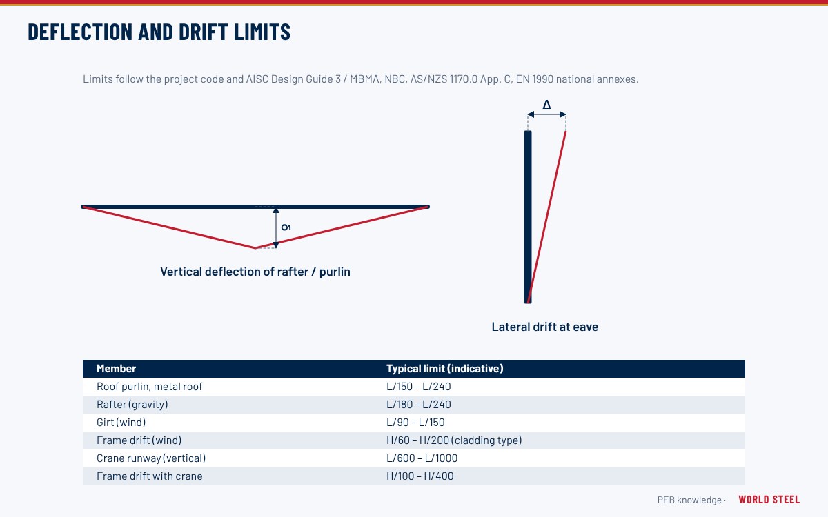
- Deflection: typical vertical limits are span/600 (CMAA Class A–C), span/800 (Class D) and span/1000 (Class E–F); lateral span/400 (AISC Design Guide 7).
- Frame drift at runway level: commonly about H/100 for pendant-operated and H/240 for cab-operated cranes (AISC Design Guide 3).
Rails, connections and fatigue detailing
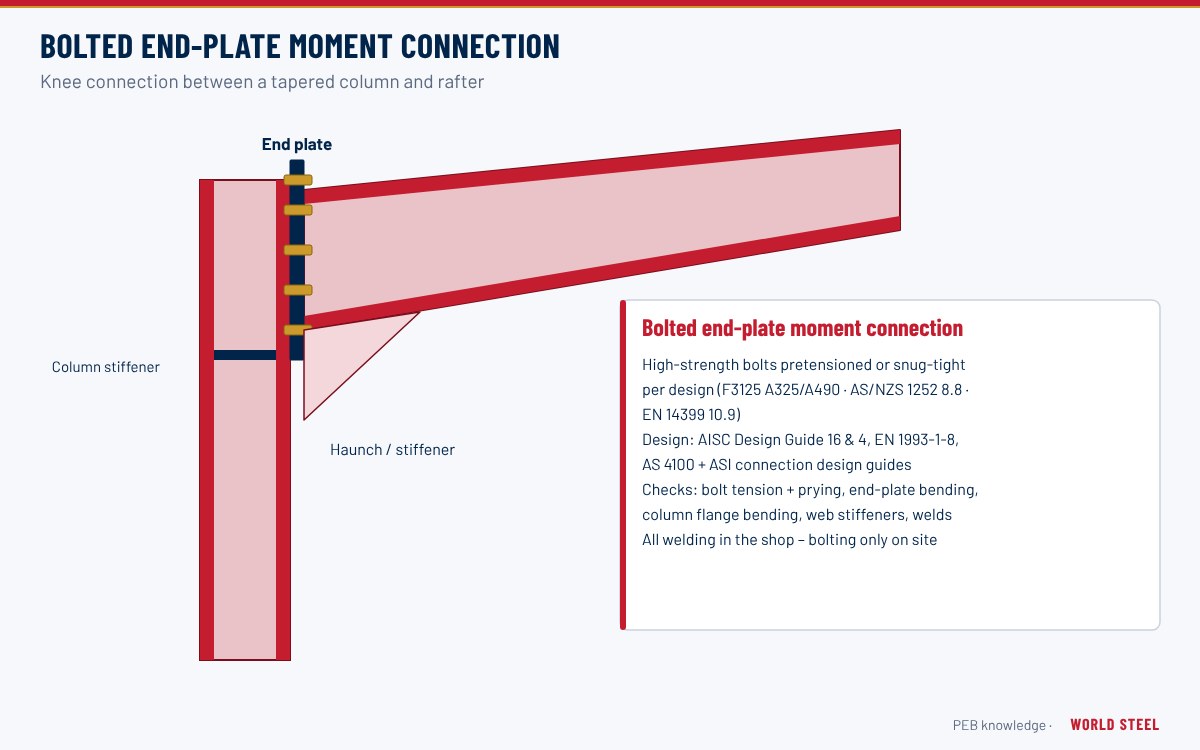
Rails (ASCE or DIN/JIS profiles, or square bar for light cranes) are fixed with adjustable clips that allow alignment and permit replacement. Elastomeric pads reduce noise and wear. Runway beams are connected to brackets with bolts in slotted holes for alignment, and the top flange is tied to the column with a flexible connection that transfers lateral load but allows end rotation – rigid ties crack under fatigue. Welds subject to repeated stress, such as web-to-top-flange welds, should be complete joint penetration or properly sized fillets per the fatigue category, and stiffener ends should be detailed to avoid stress concentrations. End stops, conductor bar brackets and walkway supports are part of the runway package. Welding follows AWS D1.1, AS/NZS 1554.1 (with SP category where specified) or EN 1090-2 with execution class as specified – see connection design.
Erection tolerances and maintenance
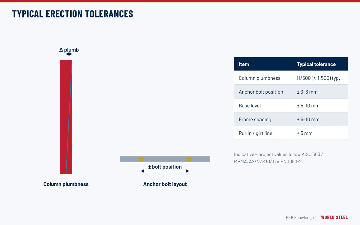
Runway alignment is critical to crane performance: span between rails, rail straightness, level and step at joints must meet the crane manufacturer's and code tolerances (for example CMAA 70, AS 1418.18 and EN 1090-2 tables). Survey the runway after erection and before crane commissioning, and periodically thereafter. Inspect bolts, rail clips, end stops and welds for fatigue cracks; see erection tolerances.
World Steel fabricates runway girders, brackets, stops and rail fixings as part of its crane runway packages, designed together with the primary frame for the supplied crane data.
المعايير حسب المنطقة
| المنطقة | الرمز | النطاق |
|---|---|---|
 United States |
ASCE 7-22 Sec. 4.9 | Crane loads – impact, lateral and longitudinal forces |
| United States |
AISC 360-22 App. 3 | Fatigue design of steel members |
| United States |
CMAA 70 / 74 | Specifications for top-running and single-girder cranes |
 Canada |
CSA S16-19 | Crane-supporting structures and fatigue provisions |
 Australia / NZ |
AS 1418.18 | Cranes – crane runways and monorails |
 Europe |
EN 1991-3 | Actions induced by cranes and machinery |
| Europe |
EN 1993-6 | Design of crane supporting structures |
الأسئلة المتكررة
What crane information is needed to design a runway?
Crane capacity, span, service class, maximum wheel loads and spacing, crane and trolley weights, hook approach, operation type (pendant, cab or radio) and rail type – ideally the crane manufacturer's data sheet.
When are brackets not enough?
For heavy cranes, high duty classes or tight drift limits, stepped columns or separate crane columns are more economical and stiffer than large cantilever brackets.
Why do runway beams need fatigue design?
Each crane pass applies a full load cycle to the beam and its welds. Over the building life, millions of cycles can initiate cracks at weld details that would be adequate for static load.