 ENEnglish
 VITiếng Việt
 ZH中文
 KO한국어
 JA日本語
 FRFrançais
 ITItaliano
 PTPortuguês
 ESEspañol
 HEעברית
 ARالعربية

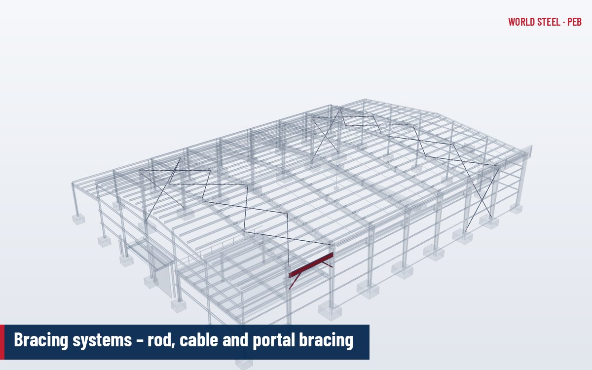
Why a PEB needs bracing
Portal frames are stiff and strong in their own plane but have almost no resistance along the building length. Bracing provides the longitudinal stability. It also keeps the frames square and plumb during erection and stabilises the roof plane, which collects wind from the endwalls.
A typical bracing system has three parts:
- Roof bracing – diagonal X-bracing in the roof plane of one or more bays, forming a horizontal truss with the rafters and struts;
- Wall bracing – X-bracing in the side walls of the same bays, taking roof forces down to the foundations;
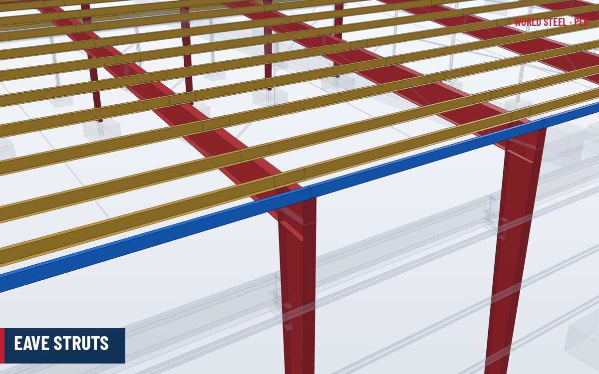
- Struts – the eave struts and strut purlins that tie all other frames to the braced bays.
Load path of the bracing system
Wind on an endwall is collected by the endwall columns, whose top reactions enter the roof plane. The roof bracing truss carries these forces to the side walls, the eave struts carry them along the building, and the wall bracing takes them down to the column bases and anchor bolts. Longitudinal seismic forces, crane braking forces and frame stability (notional) forces follow the same path.
Braced bays are usually the first or second bay from each end, plus intermediate bays in long buildings – common practice limits the distance between braced bays, for example to around 50–60 m, depending on design.
Bracing types and typical sizes
| Type | Typical size | Notes |
|---|---|---|
| Round rod bracing | 12–32 mm diameter | Tension-only; hillside washers or brackets at web; most common |
| Cable (wire strand) bracing | 6–16 mm galvanised strand | Tension-only; eye bolts and turnbuckles; light and fast |
| Angle bracing | L50–L100 | Can act in compression when sized; used for higher forces |
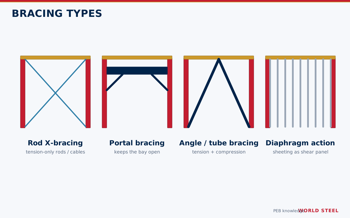
| Portal bracing | Built-up or hot-rolled portal in the wall | Where X-bracing would block doors or openings |
| Fixed-base or wind columns | Frame members | Alternative where no bracing can be placed |
Rods are typically plain or galvanised bar with threaded ends; strand is hot-dip galvanised. Bracing material is supplied with nuts, hillside washers, clevises or eye bolts as detailed.
Choosing a bracing alternative
| System | Advantages | Limitations |
|---|---|---|
| Rod X-bracing | Cheapest; simple to tension; standard details | Tension-only; blocks the bay; seismic restrictions in high categories |
| Cable (strand) bracing | Very light; quick to install; long lengths without splices | Needs proprietary fittings; creep and re-tensioning must be considered |
| Angle or hollow-section bracing | Works in tension and compression; stiffer | Heavier; more connection work |
| Portal bracing (wall portal) | Leaves the bay open for doors, docks and traffic | Higher steel weight; more flexible than X-bracing |
| Knee bracing | Short diagonals near the eave keep most of the bay clear | Introduces bending into columns; limited capacity |
| Fixed-base or wind columns | No diagonals at all | Large column moments, heavy footings; drift control difficult |
| Roof diaphragm | Uses the sheeting already present; can replace roof rod bracing | Requires designed fasteners, side-lap stitching and control of openings (AISI S310, EN 1993-1-3 stressed-skin design); standing seam roofs generally cannot be used |
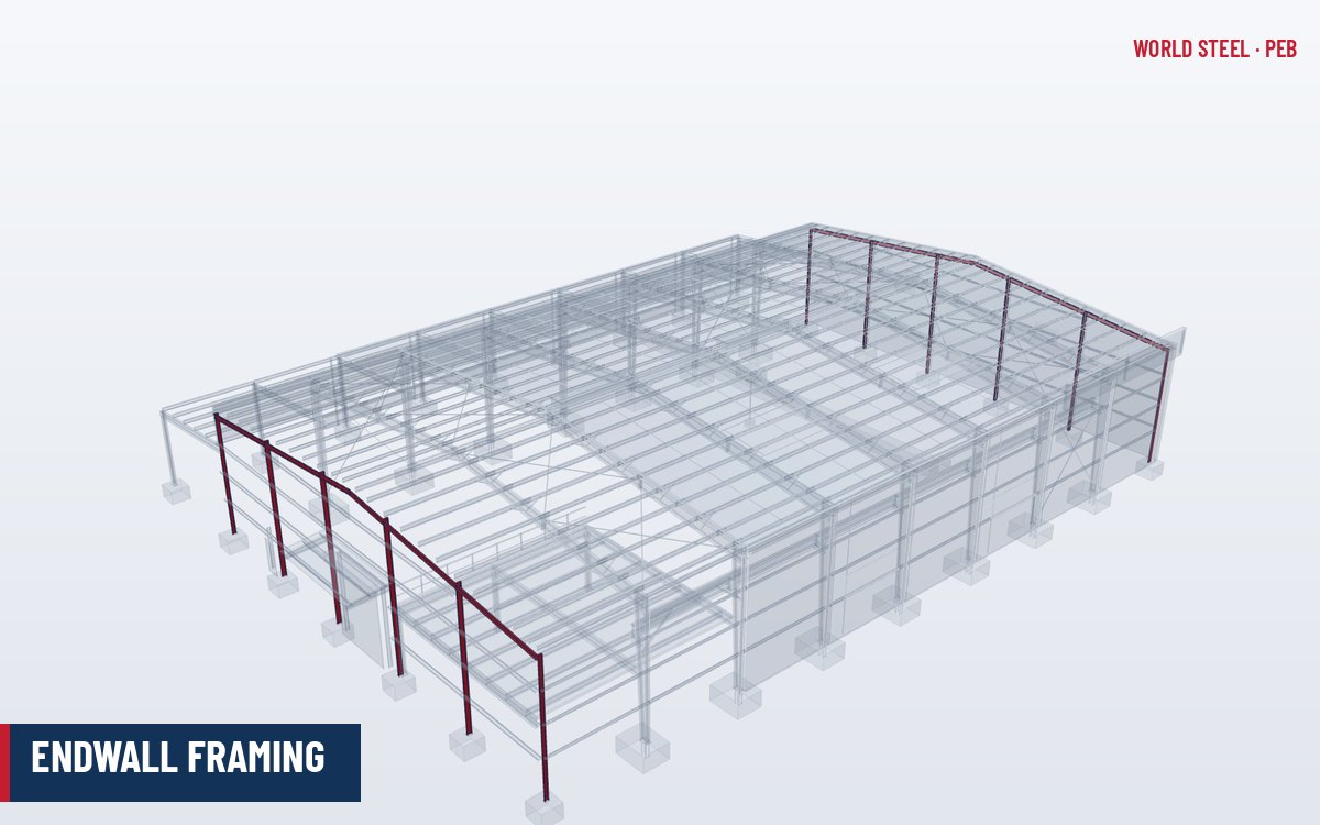
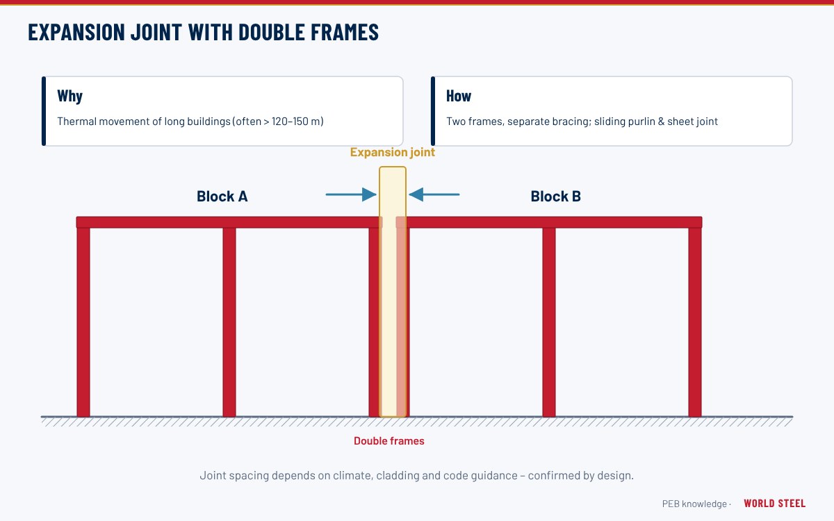
Endwalls need bracing in their own plane too: rod bracing between endwall posts, or a rigid frame endwall where large openings leave no room for diagonals. On long buildings with expansion joints, each block between joints needs its own braced bay, ideally near its centre so that thermal movement is not restrained at both ends. Temporary erection bracing is separate from the permanent system and is removed only when the permanent bracing and sheeting are complete.
Design considerations
- Tension-only design: slender rods and cables are assumed to work in tension only; the opposite diagonal takes reversed loads.
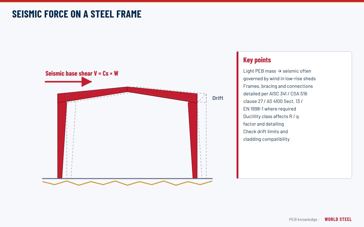
- Seismic: in higher seismic categories codes restrict tension-only systems or require specific ductility and connection detailing (AISC 341-22, CSA S16-19 clause 27, NZS 3404, EN 1998-1).
- Openings: door and window positions must be fixed early so braced bays can be placed; portal bracing costs more.
- Eccentricity: bracing connections should align with the strut and frame centrelines to avoid secondary bending.
- Crane buildings need stiffer bracing below the crane beam to resist longitudinal braking forces.
- Diaphragm action of sheeting is usually not relied on in PEB unless specifically designed.
Fabrication and installation
World Steel cuts and threads rods, assembles cable kits with fittings, and fabricates portal frames from built-up plate. Holes for bracing are made in the frame webs during fabrication. On site:
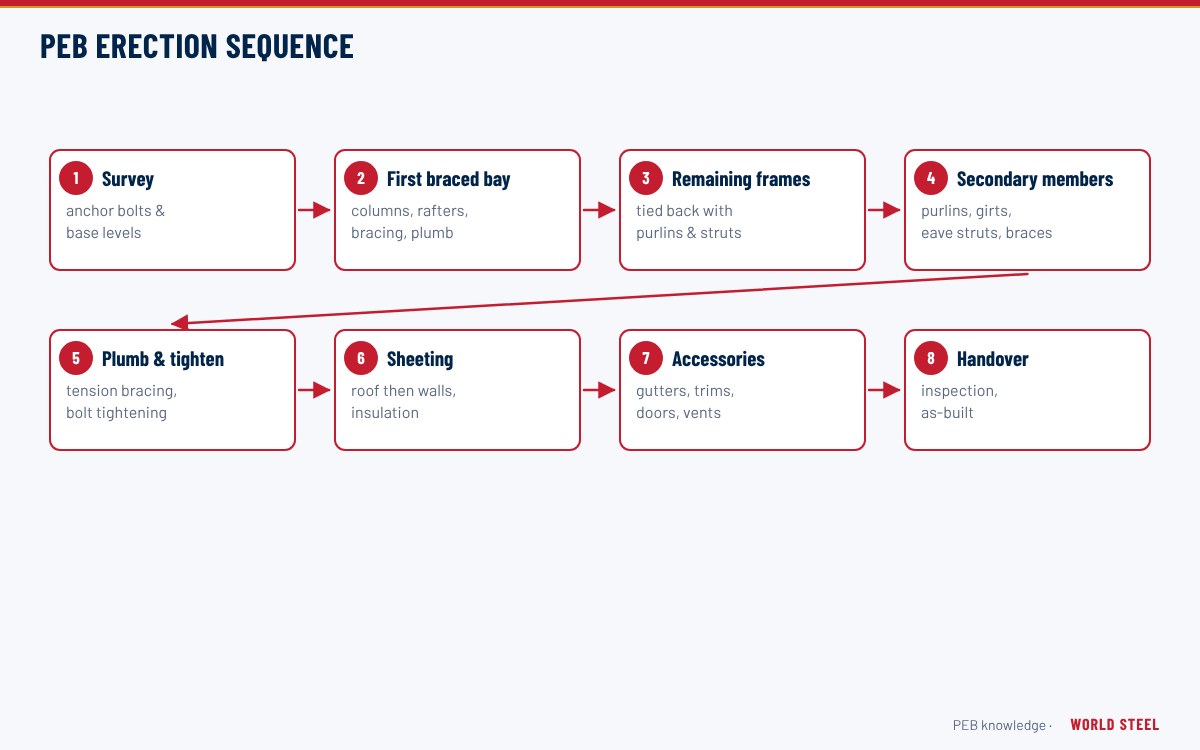
- Erect the first braced bay with its frames, struts, roof and wall bracing as a stable unit.
- Plumb and square the bay, then tension rods or cables until taut without bowing the frames.
- Erect the remaining frames from the braced bay using temporary bracing as required.
- Recheck tension after the roof is sheeted.
See the erection sequence for the full procedure.
Common mistakes and quality checks
- Bracing left slack – loose rods do not prevent sway.
- Over-tensioning that pulls frames out of plumb.
- Bracing removed to make room for a door added during construction.
- Missing hillside washers, so nuts bear on an inclined surface.
지역별 기준
| 지역 | 기준 | 범위 |
|---|---|---|
 United States |
AISC 360-22 / AISC 341-22 / ASCE 7-22 | Bracing design, seismic provisions and loads |
 Canada |
CSA S16-19 / NBC 2020 | Bracing and seismic requirements |
 Australia / NZ |
AS 4100:2020 / AS 1170.4 | Steel design and earthquake actions |
 Europe |
EN 1993-1-1 / EN 1998-1 | Bracing and seismic design |
자주 묻는 질문
Where are braced bays located?
Usually in an end bay or the second bay at each end, with intermediate braced bays in long buildings. The design drawings show their positions.
What if bracing blocks a door?
Portal bracing or a rigid frame in the wall plane can replace X-bracing in that bay, but it is heavier and should be planned at design stage.
Is cable bracing as good as rod bracing?
Both are tension-only systems. Cable is lighter and quick to install; rod bracing is robust and common. The choice depends on forces, code requirements and detailing.
What can replace X-bracing where a large door is needed?
A portal frame in the wall line is the usual alternative: it leaves the bay open while carrying the longitudinal forces in bending. Knee bracing, fixed-base columns or relocating the braced bay to another bay are other options, each checked by the designer.