 ENEnglish
 VITiếng Việt
 ZH中文
 KO한국어
 JA日本語
 FRFrançais
 ITItaliano
 PTPortuguês
 ESEspañol
 HEעברית
 ARالعربية

What a jack beam is
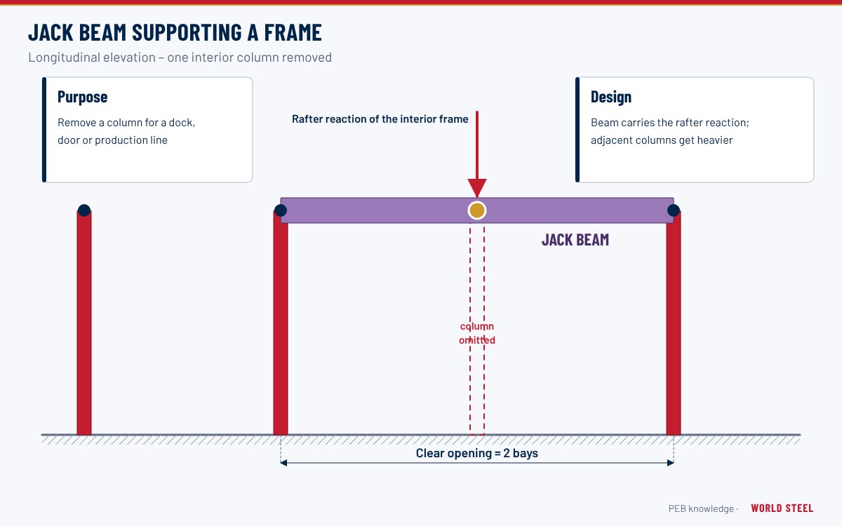
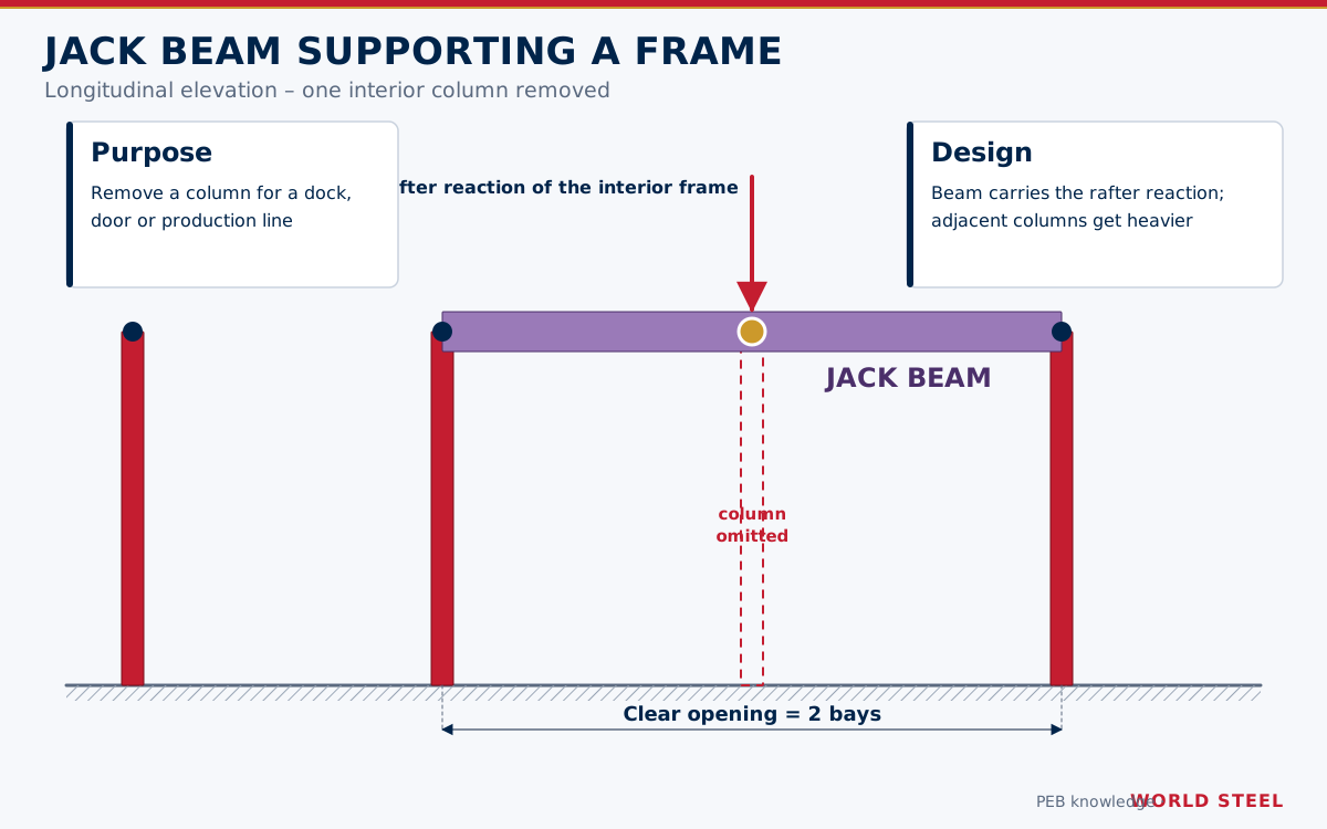
A jack beam (also called a jack truss when built as a truss, or a transfer beam) is a horizontal primary member that spans between two columns and supports the rafter of an intermediate frame whose column has been removed. It is the standard way of creating a column-free bay in a pre-engineered building without making every bay longer and every purlin deeper.
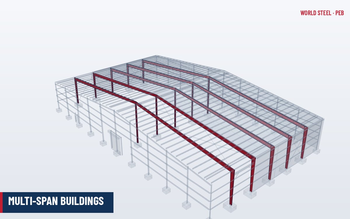
Jack beams appear in two main locations. In a sidewall, a jack beam at eave level replaces an exterior column to form a wide opening – for truck loading, aircraft or equipment access, or a long run of doors. In the interior of a multi-span building, a jack beam at the top of the interior columns lets one or more interior columns be omitted to clear a production line, crane path or vehicle route.
Typical arrangements
| Location | Typical clear bay | Loads carried |
|---|---|---|
| Sidewall, one column omitted | 12–18 m (two standard bays) | Rafter reaction, wall wind load, eave strut and girt loads |
| Sidewall, long opening | Up to about 20–24 m | As above; deflection often governs |
| Interior, multi-span | 12–18 m along the building | Mainly vertical rafter reaction; lateral restraint from roof bracing |
| Endwall | Wide door in an endwall | Endwall rafter reaction and wind on the header zone |
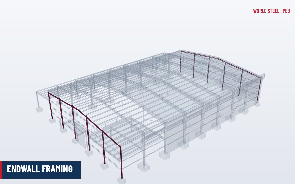
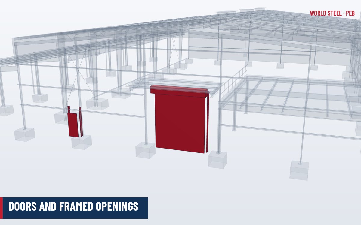
Jack beams are normally welded I-sections, straight or tapered, connected to the supporting columns with bolted end plates or seated connections. For very long or heavily loaded spans a trussed jack girder may be lighter. In endwalls the equivalent member is often called a header; see endwall framing and doors and framed openings.
Design considerations
- Point load from the rafter. The supported rafter delivers a large concentrated reaction, including uplift under wind. The jack beam, its connections and the two supporting columns must all be checked for it.
- Change in frame behaviour. The intermediate frame loses its column, so it no longer acts as a portal at that side. Its rafter becomes a beam or a frame with one flexible support, and its moments and base reactions change.
- Deflection compatibility. Jack beam deflection lowers the supported rafter, which can disturb roof drainage, door clearances and crane rails. Typical limits are span/360 to span/600 for vertical deflection, tighter when doors or cranes are attached.
- Lateral and torsional restraint. In sidewalls the jack beam also resists wind on the wall and must be braced at the rafter connection; interior jack beams rely on roof bracing and flange braces.
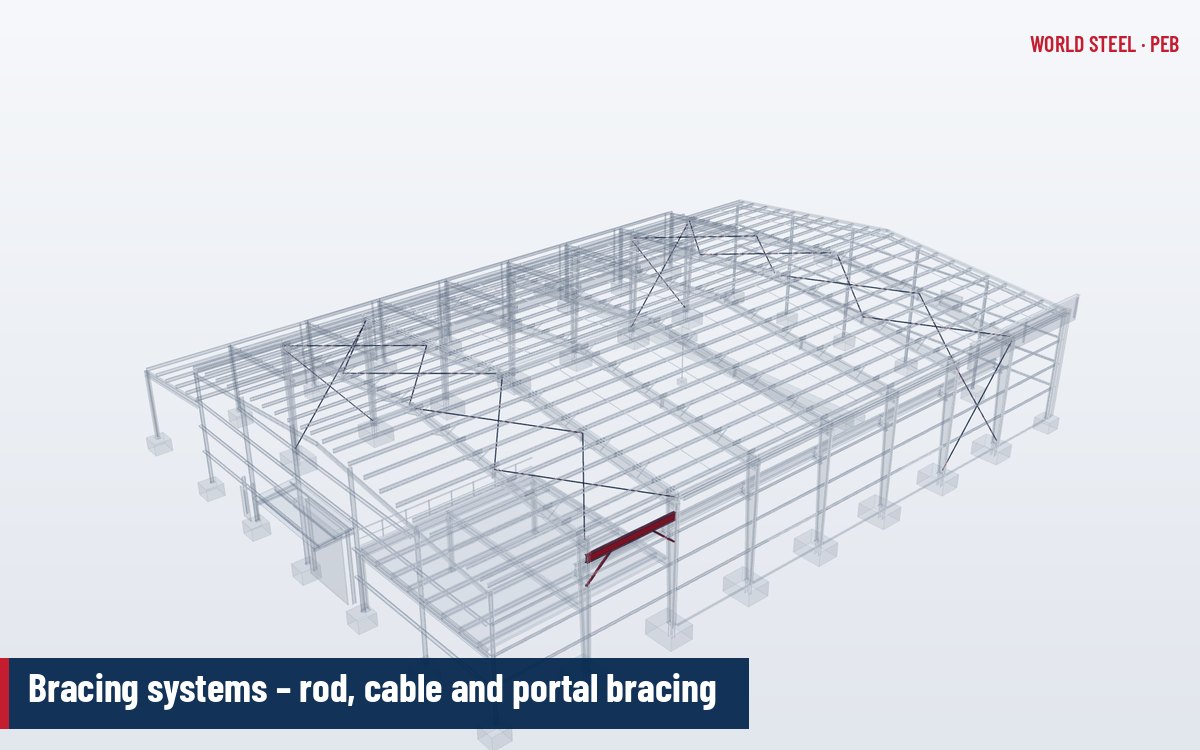
- Longitudinal bracing. Removing a column may remove a braced bay. Wall bracing should be relocated or replaced with portal bracing – see bracing systems.
- Foundations. The two columns either side of a jack beam carry roughly double the usual reactions; tell the foundation designer early.
Ask for jack beams at the layout stage. Adding one after the frames are designed changes the column reactions, bracing layout and foundations.
Fabrication and erection
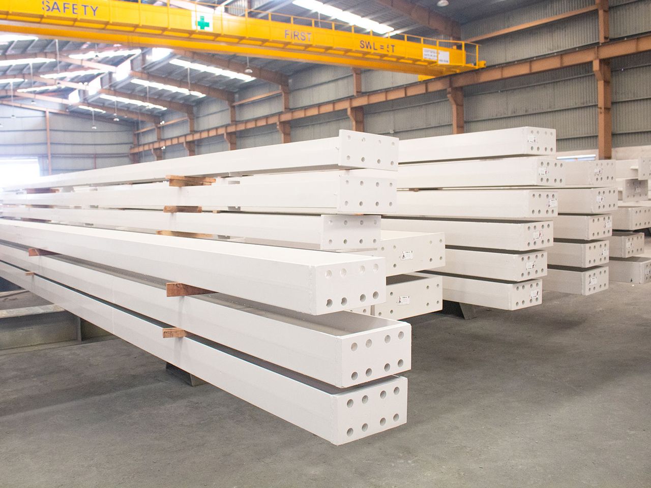
Jack beams are fabricated on the same automatic welding lines as columns and rafters, with stiffeners at the rafter seat and at the support connections. On site the jack beam is erected before the intermediate rafter, and temporary propping may be needed until the roof bracing and purlins are complete. Camber may be specified for long spans to offset dead-load deflection.
Jack beams from World Steel
World Steel designs jack beams as part of the primary frame, checking the supported frame, columns, connections and bracing together, and lists the increased reactions on the anchor bolt plan. Typical applications include logistics centres with wide dock openings, workshops and aircraft hangars.
Tiêu chuẩn theo khu vực
| Khu vực | Tiêu chuẩn | Phạm vi |
|---|---|---|
 United States |
AISC 360-22 / ASCE 7-22 | Member design, concentrated loads and load combinations |
 Canada |
CSA S16-19 | Design of steel structures |
 Australia / NZ |
AS 4100:2020 | Steel structures – beams with concentrated loads |
 Europe |
EN 1993-1-1 / EN 1993-1-5 | Member design and plated elements under patch loads |
Câu hỏi thường gặp
What is the longest bay a jack beam can create?
Two standard bays, typically 12–18 m, are common. Spans of about 20–24 m are feasible, but jack beam depth, deflection and column reactions grow quickly.
Can a jack beam be added to an existing PEB?
Sometimes, but it requires a full structural check of the affected frames, columns, bracing and foundations, and usually temporary propping during the change.
Is a jack beam cheaper than longer bays everywhere?
Usually yes. Increasing every bay to 15 m would need deeper purlins and girts throughout; a jack beam concentrates the extra steel in one location.