 ENEnglish
 VITiếng Việt
 ZH中文
 KO한국어
 JA日本語
 FRFrançais
 ITItaliano
 PTPortuguês
 ESEspañol
 HEעברית
 ARالعربية

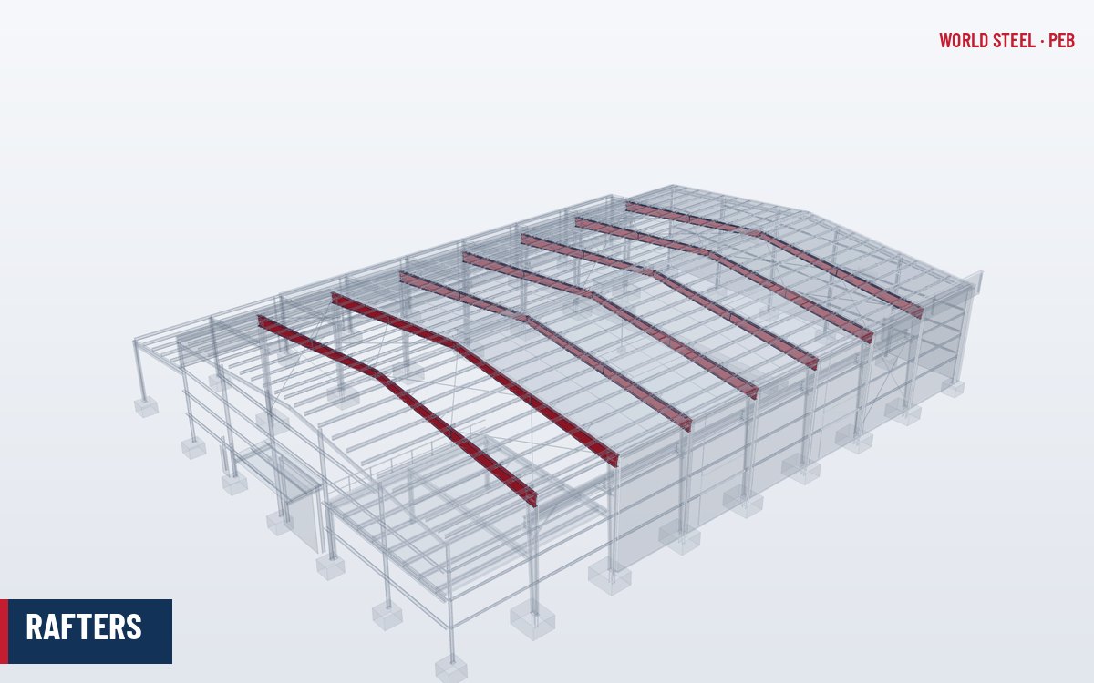
Definition and function
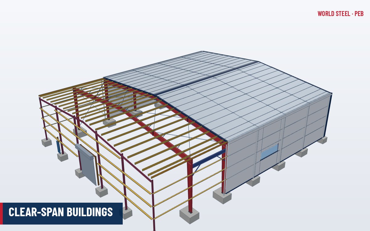
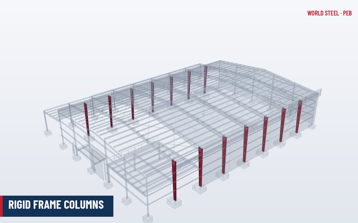
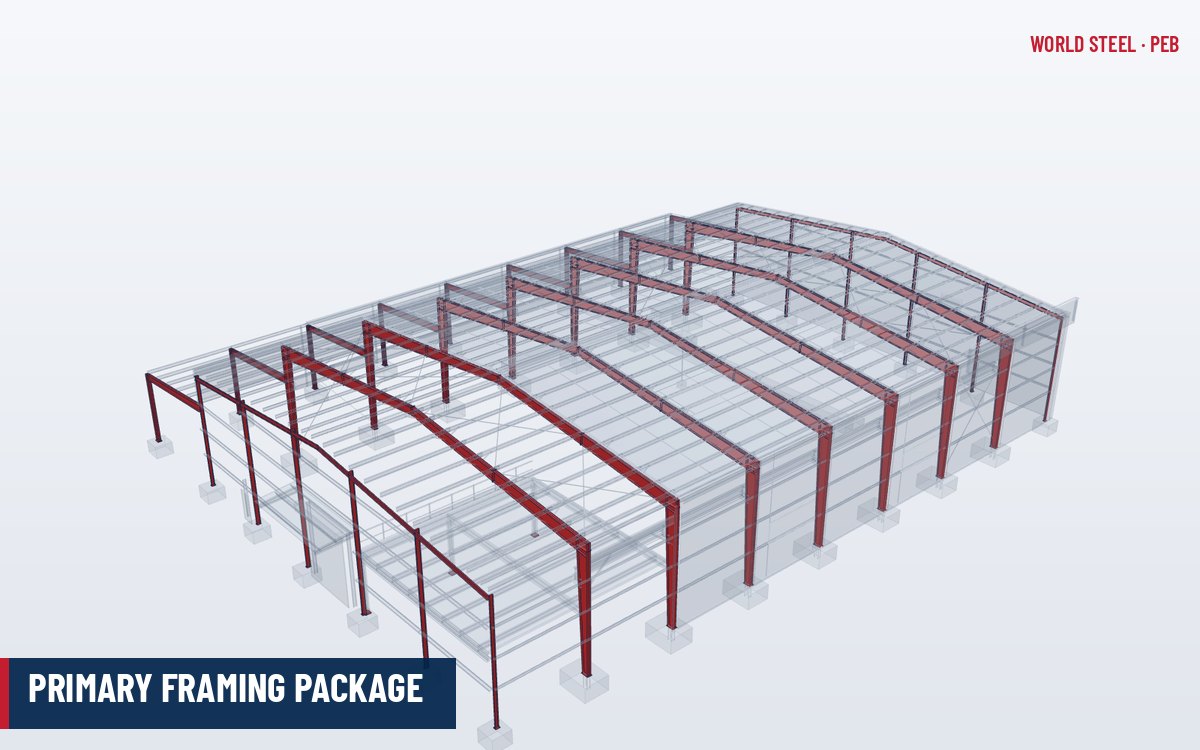
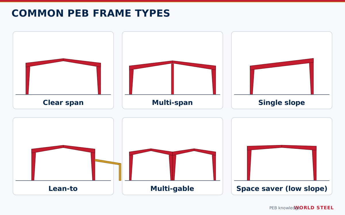
A rafter is the sloping roof member of a PEB portal frame. In a symmetrical gable frame two rafters meet at the ridge and connect to the rigid frame columns at the knees. Rafters support the purlins, act in bending and axial compression as part of the moment frame, and – in clear-span buildings – carry roof loads across spans that commonly reach 30 to 60 m and in special cases more.
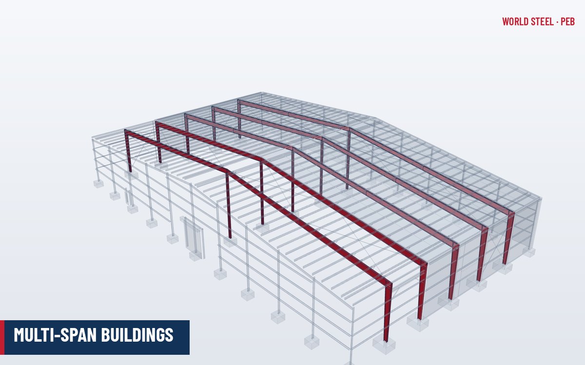
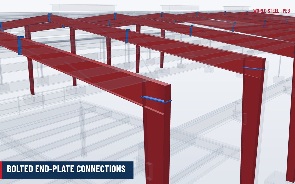
Rafters are almost always made of several shipping pieces joined by bolted splices, because a single piece is limited by container or truck length. In multi-span frames they are continuous over interior columns, which reduces their depth considerably compared with a clear span.
Rafters in the load path
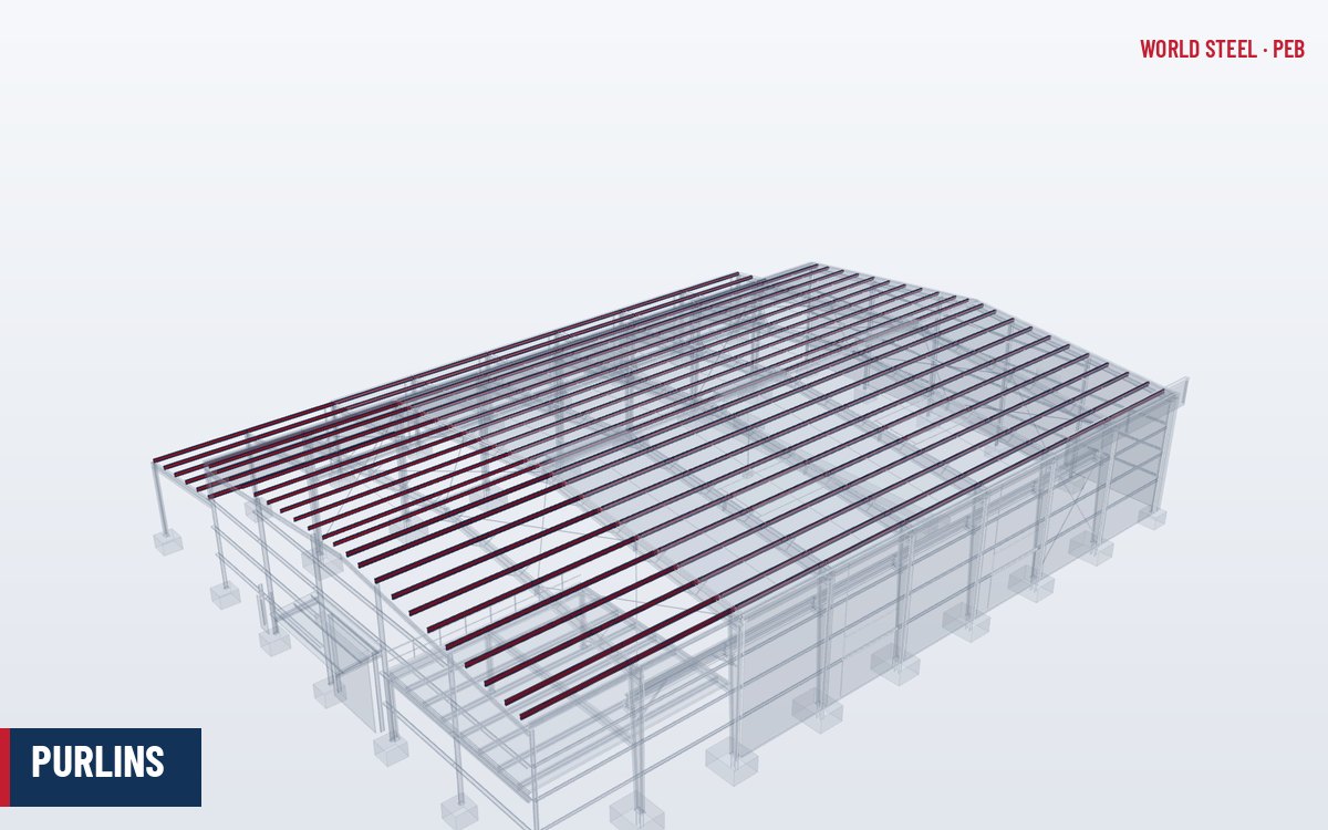
Purlins deliver roof loads to the rafter top flange at roughly 1.2–1.8 m centres. The rafter carries these as bending moment, which is greatest (negative) at the knee and changes sign towards midspan, and as shear and axial compression into the column. The horizontal thrust at the base of a gable frame is a direct consequence of the rafter slope and frame action.
Under wind uplift the moments reverse: the bottom (inner) flange, normally in tension at midspan, goes into compression. This is why flange braces from purlins to the inner flange are essential for rafter stability.
Typical shapes, sizes and slopes
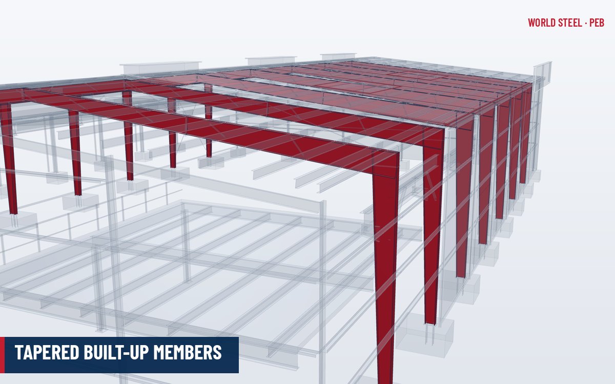
Rafters are tapered built-up I-sections: deep at the haunch where the moment is greatest, shallower towards midspan, and sometimes deepening slightly at the ridge.
| Clear span | Depth at haunch | Depth at midspan | Flange width |
|---|---|---|---|
| 15–24 m | 450–700 mm | 300–450 mm | 150–200 mm |
| 24–36 m | 650–1,000 mm | 400–600 mm | 180–250 mm |
| 36–60 m | 900–1,500 mm | 550–900 mm | 200–350 mm |
Common roof slopes are 1:10 to 1:20 for low-rise industrial buildings; 1:12 is widely used. Through-fastened trapezoidal roofs usually need a steeper minimum slope than standing seam roofs, so the roof system must be chosen before the frame geometry is fixed. Plate grades match the columns: ASTM A572 Gr 50, AS/NZS 3678 Grade 350 or EN 10025-2 S355.
| Rafter type | Typical section | Notes |
|---|---|---|
| Clear-span gable rafter | Tapered built-up I, moment connected at knee and ridge | Deepest at the haunch; ridge splice by end plates |
| Multi-span rafter | Built-up I, often near-prismatic between supports | Continuous over interior columns; bolted cap-plate connection |
| Single-slope rafter | Tapered built-up I | Unsymmetrical frame; one high and one low knee |
| Lean-to rafter | Built-up I, hot-rolled or cold-formed for light spans | Usually pinned at both ends; stability from the main frame |
| Endwall rafter (post-and-beam) | Cold-formed C, hot-rolled channel or light built-up I | Simply supported between endwall posts; carries roof bracing reactions |
| Cantilever extension | Built-up stub bolted to the column or rafter | For eave overhangs and canopies; see roof extensions |
Design considerations
- Stability of the inner flange under uplift and near the haunch, controlled by flange brace spacing.
- Deflection limits – vertical deflection (often span/180 to span/240, tighter under brittle ceilings or sprinklers) and ponding on low-slope roofs.
- Splice positions located near points of low moment and within transport length limits (typically up to about 12 m per piece for 40 ft containers).
- Collateral load for sprinklers, lighting, solar panels and services must be stated by the owner; it is easily underestimated.
- Snow drift and ponding at roof steps, parapets and lean-to junctions in cold climates (ASCE 7-22, NBC 2020, EN 1991-1-3).
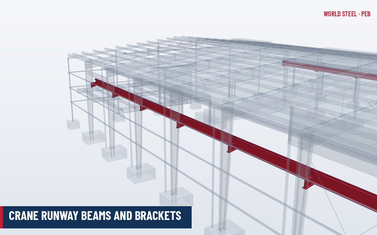
- Point loads from hoists, monorails or hanging equipment require local checks and sometimes web stiffeners.
The rafter and column are designed together as one frame, usually with second-order analysis; frame weight is optimised by varying plate thickness and taper along the member.
Fabrication, coating and installation
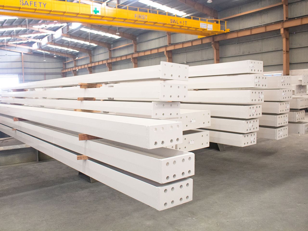
World Steel fabricates rafters on the same automatic lines as columns: CNC-cut tapered webs, submerged arc welded flanges, end plates welded square to the slope, and purlin cleats and bracing holes positioned from the 3D model. After blasting and painting, each piece is marked with its frame line and mark number, and splice bolts are packed by frame.
On site, rafter pieces are usually bolted together on the ground and lifted as a half-frame or full-frame assembly with a spreader beam, then connected at the knees. The first two frames are erected together with roof and wall bracing to form a stable braced bay before other frames follow, as described in the erection sequence.
Common mistakes and quality checks
- Splice end plates not in full contact – check fit-up gaps before tightening bolts.
- Rafter lifted at a single point, causing lateral buckling of slender sections – use spreader beams and two-point lifts.
- Purlin cleats installed on the wrong side or wrong slope direction – verify cleat orientation against the drawings.
- Ridge level and camber not checked before roof sheeting starts.
- Bolts left snug instead of pretensioned where the design calls for pretension.
Tiêu chuẩn theo khu vực
| Khu vực | Tiêu chuẩn | Phạm vi |
|---|---|---|
 United States |
AISC 360-22 / ASCE 7-22 | Member design, loads, snow and ponding |
 Canada |
CSA S16-19 / NBC 2020 | Steel design and loads including snow |
 Australia / NZ |
AS 4100:2020 / AS/NZS 1170 | Steel design and structural actions |
 Europe |
EN 1993-1-1 / EN 1991-1-3 | Steel design and snow loads |
Câu hỏi thường gặp
How deep is a PEB rafter?
Depth depends on span, loads and bay spacing. For a 30 m clear span the haunch is often 650–1,000 mm deep, tapering to 400–600 mm at midspan.
Why are rafters spliced?
Rafters for wide buildings are too long to ship in one piece. Bolted end-plate splices are placed near low-moment points so pieces fit containers and trucks.
What minimum roof slope should be used?
It depends on the roof system. Standing seam roofs can be used at low slopes (IBC permits 1/4:12 for standing seam systems), while through-fastened sheeting usually needs a steeper slope set by the sheet manufacturer and code.