 ENEnglish
 VITiếng Việt
 ZH中文
 KO한국어
 JA日本語
 FRFrançais
 ITItaliano
 PTPortuguês
 ESEspañol
 HEעברית
 ARالعربية

What purlins do
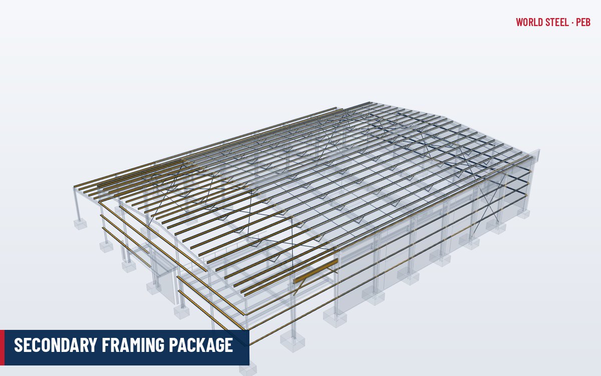
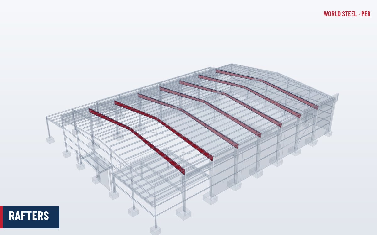
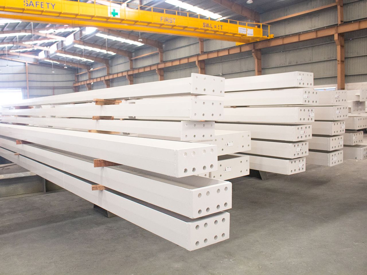
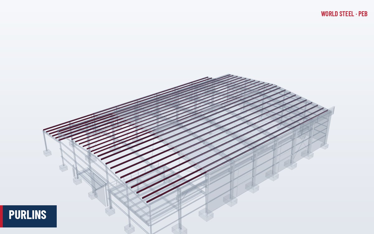
Purlins are the horizontal secondary members of the roof. They span between the rafters of adjacent frames, support the roof sheeting or standing seam panels, and transfer roof loads to the primary frame. They also do several jobs that are less obvious:
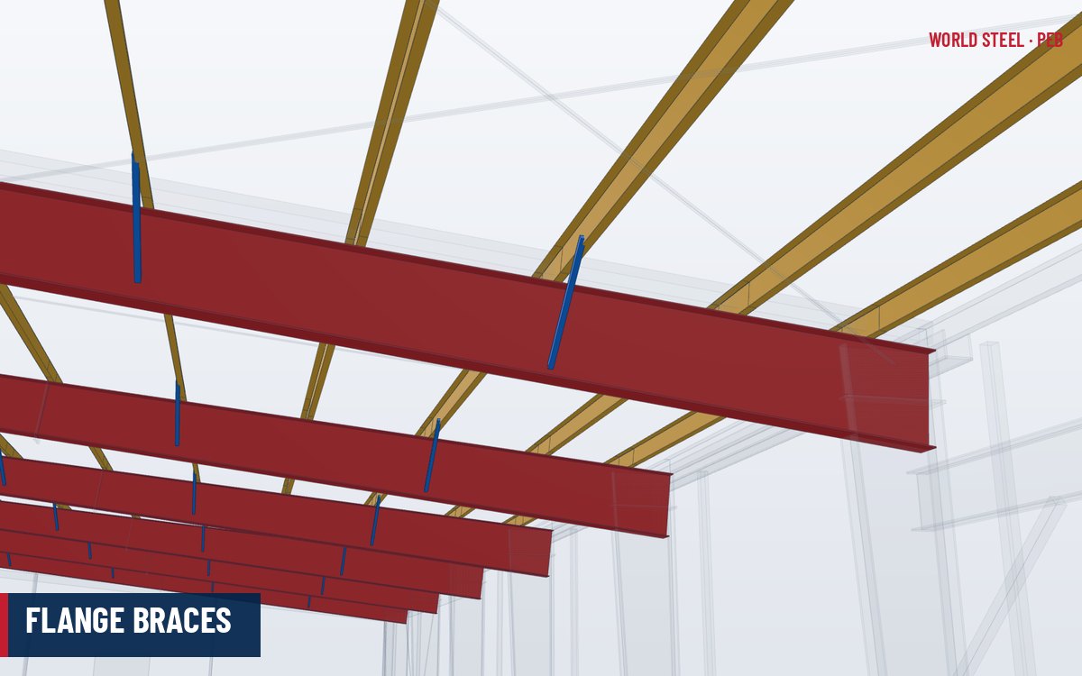
- restrain the rafter top flange and, through flange braces, the inner flange;
- act as struts in the roof bracing system;
- carry collateral loads such as sprinklers, lighting and ducts.
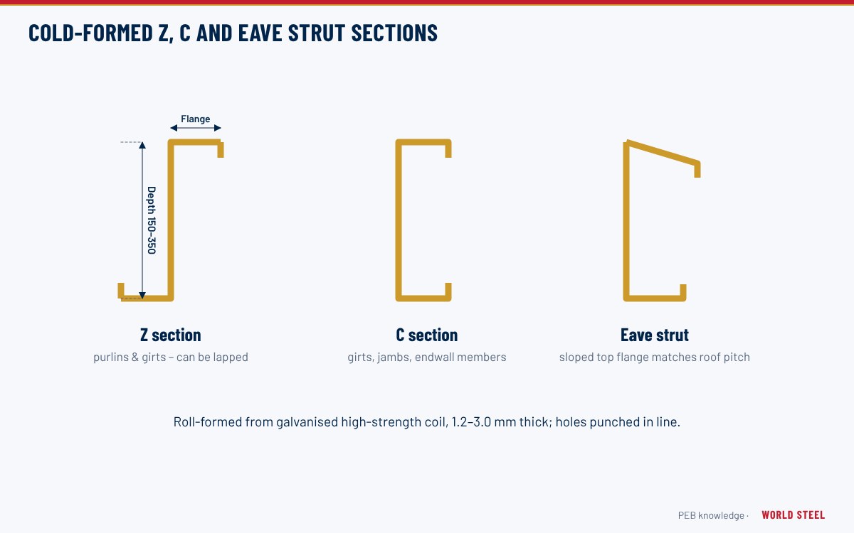
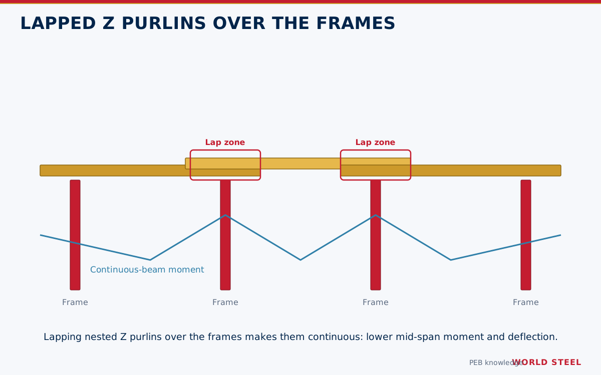
In pre-engineered buildings purlins are almost always cold-formed Z or C sections roll-formed from galvanised or bare high-strength coil.
Purlins in the load path
Roof sheeting carries dead, live, snow and wind load to the purlins at each fastener line. Purlins span 6–9 m (up to about 12 m with deep sections) between frames and deliver their reactions through cleats bolted to the rafter. Under wind uplift the load reverses, and the unrestrained bottom flange of the purlin is in compression – usually the governing case in tropical and cyclonic regions.
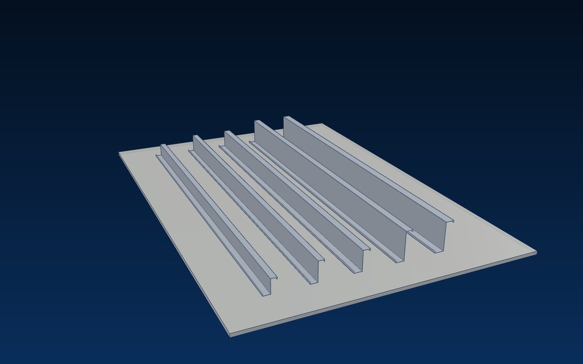
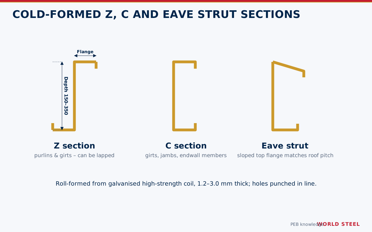
Z purlins can be nested and lapped over the frames, making them continuous across several spans. Continuity lowers midspan moments and deflection, and the double thickness at the lap is placed where the support moment is largest.
Typical sizes and materials
| Depth | Thickness | Typical bay span |
|---|---|---|
| 150 mm | 1.5–2.0 mm | 5–6 m |
| 200 mm (8") | 1.5–2.5 mm | 6–7.5 m |
| 250 mm (10") | 1.8–3.0 mm | 7.5–9 m |
| 300–350 mm | 2.0–3.0 mm | 9–12 m |
| Region | Standard and grade |
|---|---|
| US / Canada | ASTM A1011 SS or HSLAS Gr 50/55; A653 Gr 50/55 with G90 galvanizing |
| Australia / NZ | AS 1397 G450 or G500, Z275–Z450 |
| Europe | EN 10346 S350GD–S450GD + Z275 |
Purlin spacing is usually 1.2–1.8 m, set by the sheeting span capacity and wind zone; it is reduced near eaves, ridges and corners where wind suction is highest. More detail on materials is in cold-formed steel for purlins and girts.
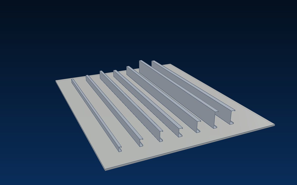
Z versus C sections, laps and special purlins
| Aspect | Z section | C section |
|---|---|---|
| Continuity | Nests and laps over supports – continuous multi-span beam | Cannot nest; normally simple spans or butt-joined with sleeves |
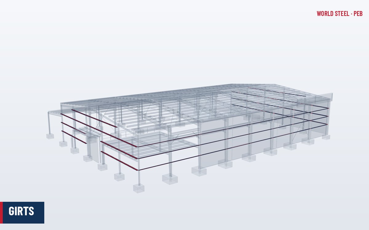
| Typical use | Roof purlins and long wall girts in repetitive bays | Short or single spans, framed openings, endwall posts and rafters, flush girts |
| Behaviour under load | Principal axes inclined – tends to deflect sideways and roll; restrained by sheeting and bridging | Load is applied off the shear centre – tends to twist; restrained similarly |
| Economy | Usually lighter for multi-bay roofs | Simpler detailing at ends and openings |
- Laps: lap length is set by design – longer laps carry more support moment – and the lap is bolted at the support and at both lap ends. Typical total laps are in the order of 0.6–1.8 m depending on span and load.
- End bays carry higher moments because they lack continuity on one side; heavier thickness or longer laps are used there.
- Ridge purlins are placed a short distance either side of the ridge to support the ridge cap and any ridge ventilator.
- Purlin extensions cantilever beyond the endwall to support a gable overhang; see roof extensions.
- Strut purlins are purlins (often doubled or heavier) at braced bays that also carry axial force from the roof bracing.
Design considerations
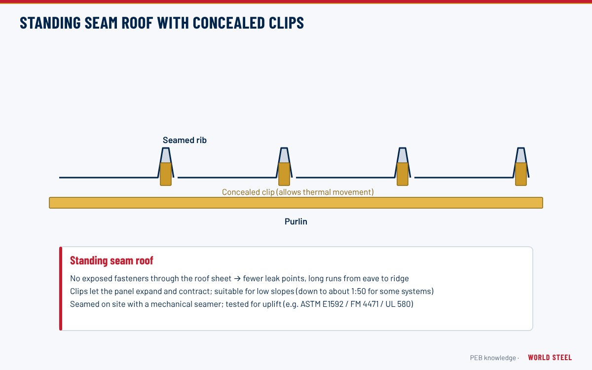
- Restraint from sheeting: through-fastened sheeting restrains the top flange; AISI S100 gives an R-factor method for uplift, and standing seam roofs are evaluated by the base test method in AISI S908. EN 1993-1-3 Section 10 and AS/NZS 4600:2018 cover the equivalent cases.
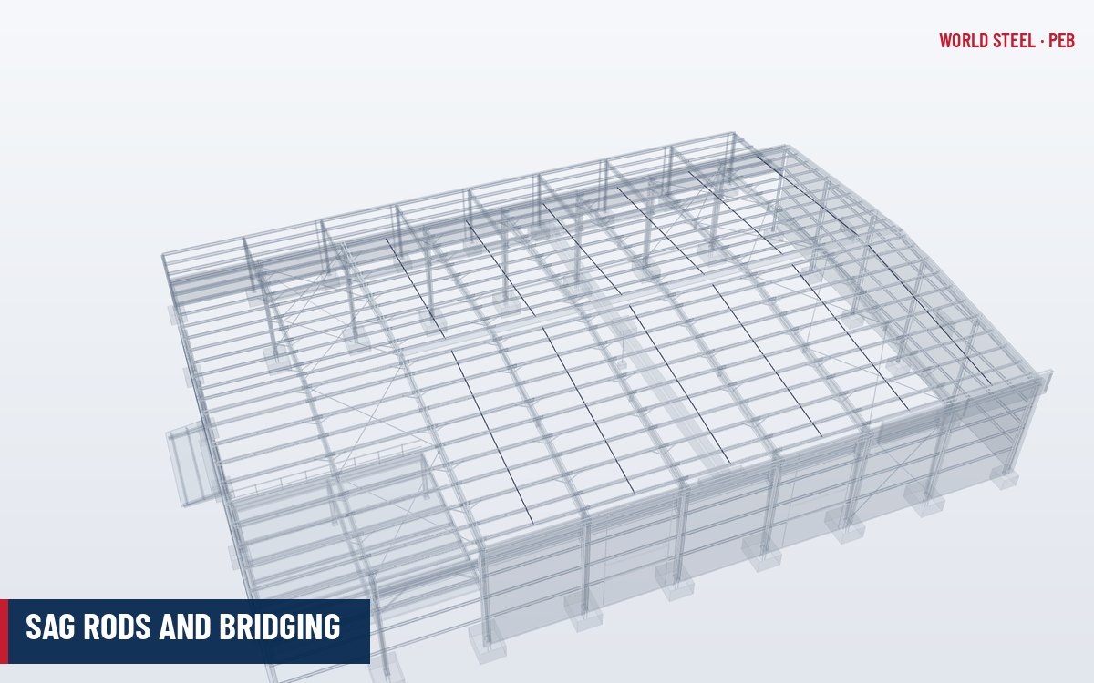
- Sag rods or bridging reduce the unbraced length of the free flange under uplift; see sag rods and bridging.
- Lap length and bolt pattern must match the design assumption of continuity.
- Anti-roll restraint: on steeper slopes Z purlins tend to roll downslope and need restraint at the ridge or anti-sag systems.
- Deflection limits under wind and gravity, typically span/150 to span/240.
- Point and hanging loads must be applied at the shear centre or via approved clips.
Fabrication, coating and installation
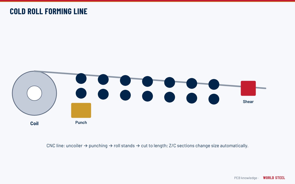
World Steel roll-forms Z and C purlins on CNC roll-forming lines that punch holes and cut to length in one pass from coil, so every purlin matches the 3D model (see cold roll forming). Pre-galvanised coil is the normal finish; hot-dip galvanising after forming or painted finishes are available for aggressive environments.
On site, purlins are bolted to rafter cleats with M12 or M16 bolts, laps are bolted as detailed, and sag rods or bridging are installed before sheeting so the roof stays straight. Purlins should be laid with the correct flange direction – Z purlins usually face upslope as shown on the erection drawings.
Common mistakes and quality checks
- Lap bolts omitted, turning a continuous design into simple spans.
- Purlins installed in the wrong flange direction, reversing the designed roll behaviour.
- Walking on unbraced purlins – fall and stability hazard.
- Wrong thickness used in end bays, where the design often uses heavier sections.
- Unauthorised hanging of services from the bottom flange.
Normes par région
| Région | Norme | Périmètre |
|---|---|---|
 United States |
AISI S100-16 (2020) / AISI S908 | Cold-formed member design; base test for standing seam purlins |
 Canada |
CSA S136-16 | North American specification, Canadian edition |
 Australia / NZ |
AS/NZS 4600:2018 | Cold-formed steel structures |
 Europe |
EN 1993-1-3 | Cold-formed members and sheeting, Section 10 purlins |
Questions fréquentes
Z purlins or C purlins?
Z purlins can be lapped to form continuous beams and are the standard choice for multi-bay roofs. C purlins are used for single spans, edges and where a flat back is needed.
What purlin spacing is typical?
Usually 1.2–1.8 m, reduced in high-suction zones near edges and corners and governed by the sheeting span tables.
Why does wind uplift govern purlin design?
Under uplift the free bottom flange, which is not attached to the sheeting, is in compression and can buckle laterally. Sag rods and bridging reduce this risk.
Why are Z purlins lapped and C purlins not?
Z sections can be nested inside each other, so two purlins overlap over a rafter and are bolted together to act as a continuous beam. C sections cannot nest, so they are normally used as simple spans or joined end to end, which makes them less efficient over several bays.