 ENEnglish
 VITiếng Việt
 ZH中文
 KO한국어
 JA日本語
 FRFrançais
 ITItaliano
 PTPortuguês
 ESEspañol
 HEעברית
 ARالعربية

What a rigid frame column does
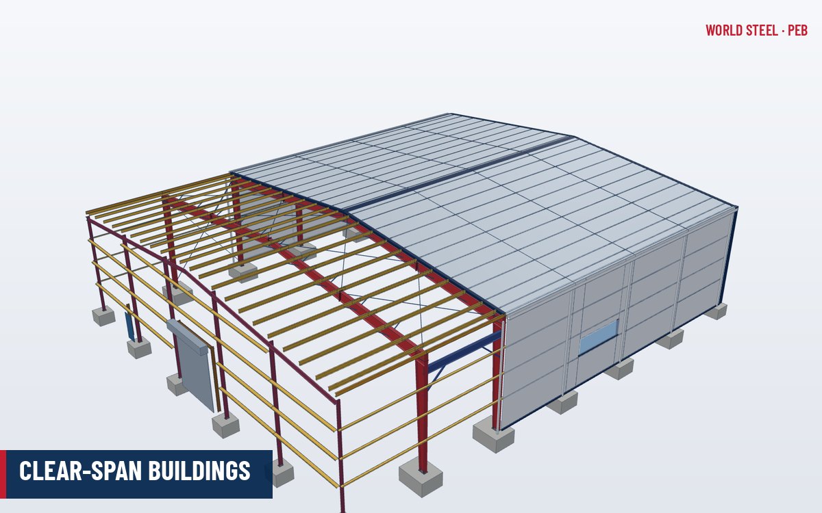
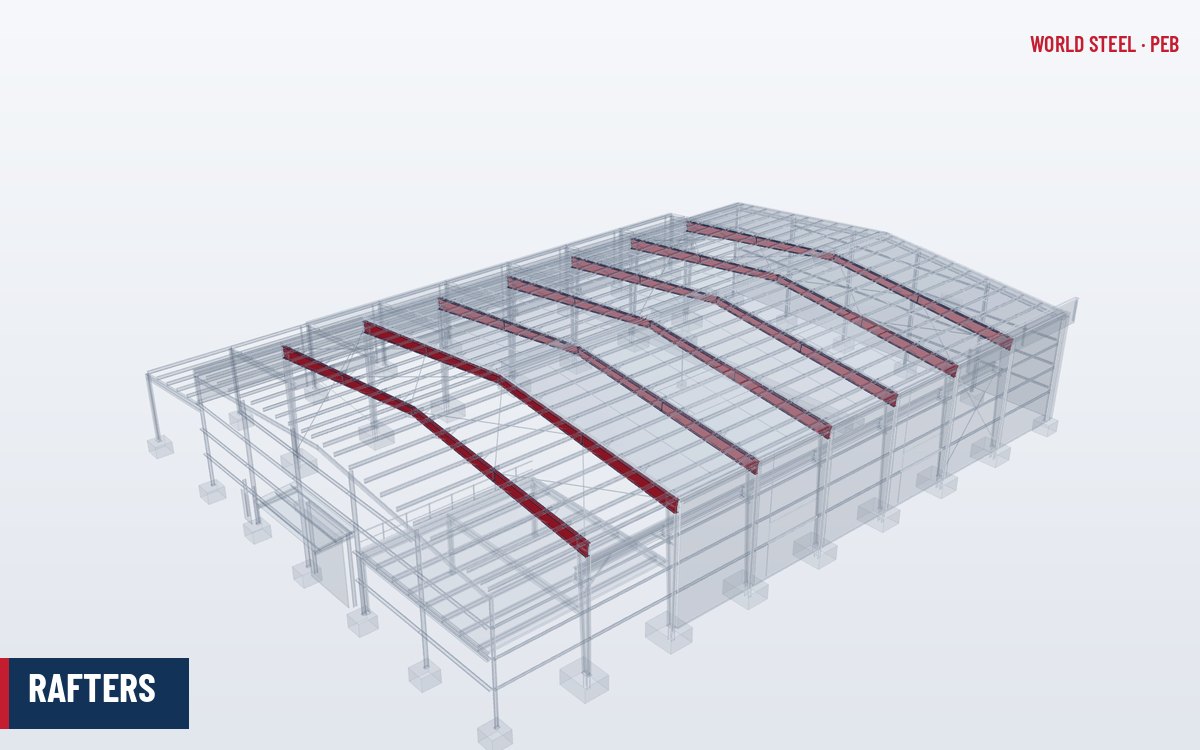
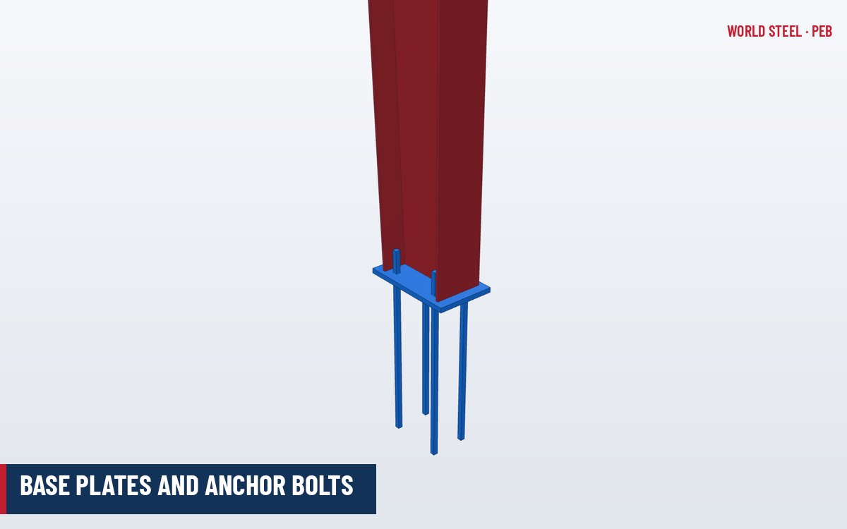
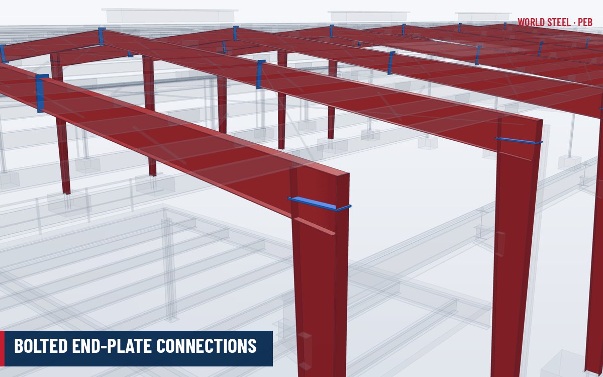
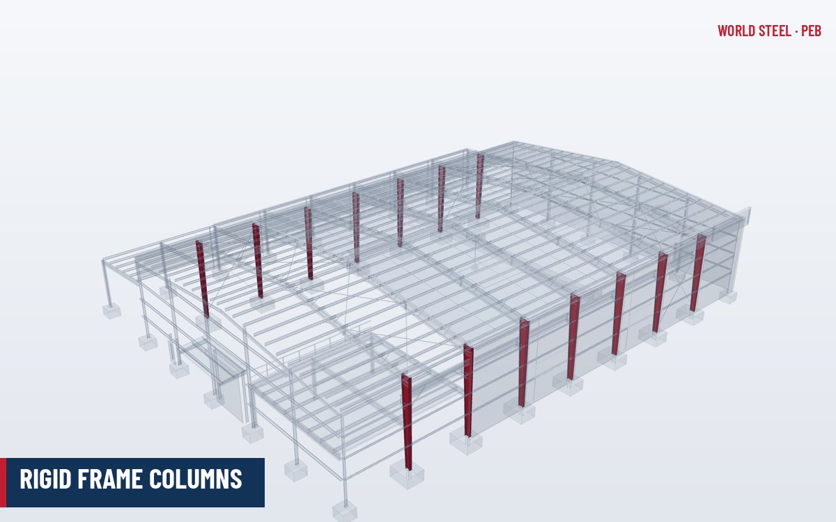
The rigid frame column is the vertical leg of the main portal frame of a pre-engineered steel building. Together with the rafters it forms a moment-resisting frame that spans the full building width and is repeated at every bay, typically every 6 to 9 m. The column is joined to the rafter by a bolted end-plate haunch connection at the knee and stands on a base plate with anchor bolts at floor level.
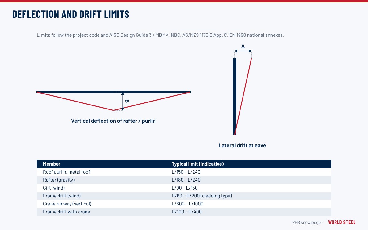
Because the knee connection is moment-resisting, the column does far more than carry vertical load. It resists the frame moment generated by roof gravity loads, it is the main element that resists transverse wind and seismic forces, and it provides the lateral stiffness that keeps eave drift within the serviceability limits set by the designer.
Place in the load path
Roof sheeting delivers load to the purlins, the purlins deliver it to the rafters, and the rafters deliver shear and moment to the column top. Wall sheeting and girts deliver wind pressure to the column outer flange along its height. The column then transfers axial force, shear and (for fixed bases) moment to the footing.
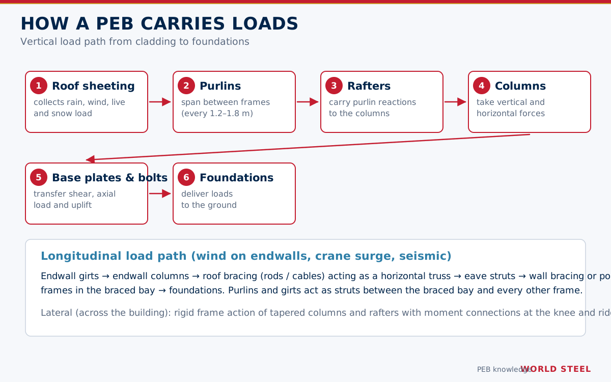
- Gravity: dead, collateral and live or snow load produce axial compression plus a large moment at the knee.
- Wind: transverse wind causes sway moments; internal pressure and uplift can put the column in net tension and reverse the moment.
- Longitudinal: forces along the building are not carried by column bending about its weak axis but by the wall bracing in braced bays.
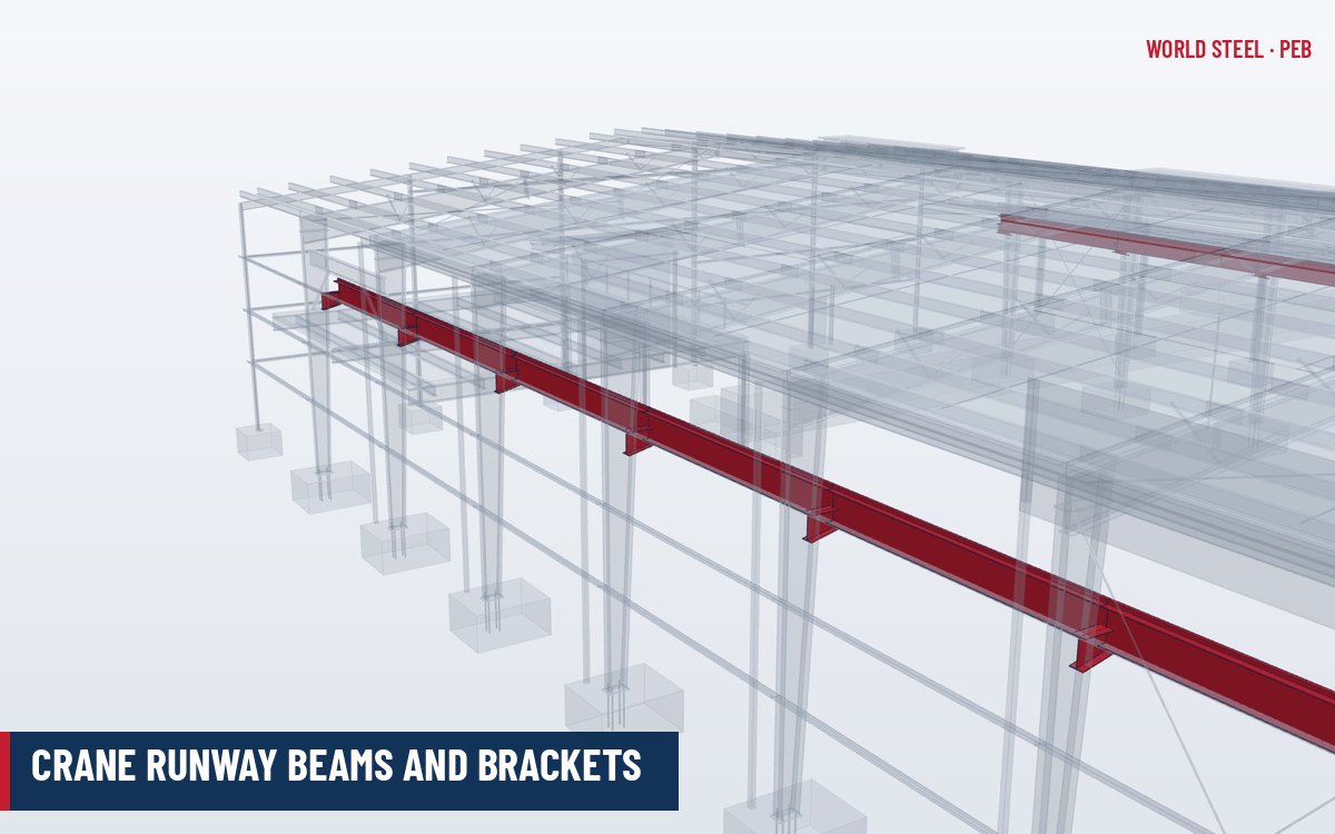
- Crane loads: in crane buildings the column carries wheel loads through a bracket and lateral surge forces.
Typical shapes, sizes and materials
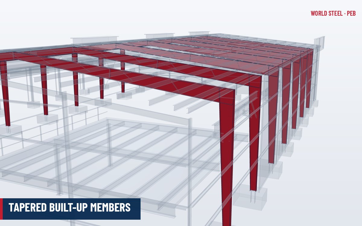
Most PEB columns are tapered built-up I-sections welded from three plates. With a pinned base the bending moment is near zero at the floor and greatest at the knee, so the web is narrow at the base and deep at the top. Where a fixed base is needed (cranes, tall eaves, tight drift limits) the column may be prismatic or tapered in the opposite sense.
| Parameter | Typical range | Notes |
|---|---|---|
| Web depth at base (pinned) | 200–450 mm | Sized for base shear and anchor bolt layout |
| Web depth at knee | 500–1,500 mm | Increases with span and eave height |
| Web thickness | 4–12 mm | Slender webs; stiffeners where shear demands |
| Flange width | 150–400 mm | Wider for long unbraced lengths |
| Flange thickness | 6–25 mm | Often varied along the length by flange splices |
| Eave height served | 4–15 m (taller with cranes) | Above ~12 m drift often governs |
Plate is normally a 345–355 MPa grade: ASTM A572 Grade 50 or A1011 HSLAS for the US and Canada, AS/NZS 3678 Grade 350 in Australia and New Zealand, EN 10025-2 S355 in Europe. Hot-rolled H-sections are used for short or heavily loaded columns where a built-up section brings no saving.
| Column type | Typical section | End conditions and role |
|---|---|---|
| Exterior rigid frame column | Tapered built-up I | Pinned or fixed base, moment connection at the knee; resists transverse loads |
| Prismatic (straight) column | Constant-depth built-up or hot-rolled I | Used for flush walls, fixed bases, mezzanine or crane support |
| Interior column (multi-span) | Pipe, square hollow section or small built-up I | Usually pinned top and bottom; carries axial load only |
| Stepped crane column | Built-up I with a reduced upper shaft | Runway bears on the step; normally fixed base |
| Endwall post (column) | Cold-formed C, hot-rolled or light built-up I | Spans from base to endwall rafter; carries endwall wind and girts |
| Wind column | Built-up or hot-rolled I | Supports a tall wall or door header where no frame column exists |
For layout planning, remember that a tapered column reduces the usable width at the knee: the horizontal clearance between the inside flanges is smallest just below the haunch, not at floor level. If racking, conveyors or cranes run close to the wall, ask for prismatic columns or flush girts at those frames.
Design considerations
- Pinned or fixed base: pinned bases reduce foundation cost; fixed bases reduce drift and frame weight but transfer moment to the footing. The decision belongs in the early design stage together with the foundation engineer.
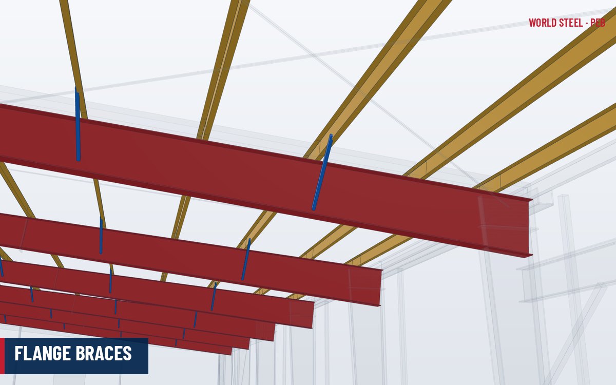
- Lateral-torsional buckling: the inner flange is in compression under gravity and is restrained by flange braces from the girts; their spacing directly controls the column size.
- Web slenderness and shear: under AISC 360-22 unstiffened webs are limited to h/tw ≤ 260; local web crippling at the knee may need stiffeners.
- Drift: eave drift limits (commonly H/60 to H/200 depending on cladding, cranes and code guidance) often govern over strength.
- Seismic: in high-seismic regions the frame may need to meet AISC 341-22, CSA S16-19 clause 27 or NZS 3404 detailing, including flange width-thickness limits.
World Steel engineers columns and the whole frame with the design team under the governing code (ASCE 7-22 with AISC 360-22, NBC 2020 with CSA S16-19, AS/NZS 1170 with AS 4100:2020, or EN 1993-1-1).
Fabrication, coating and installation
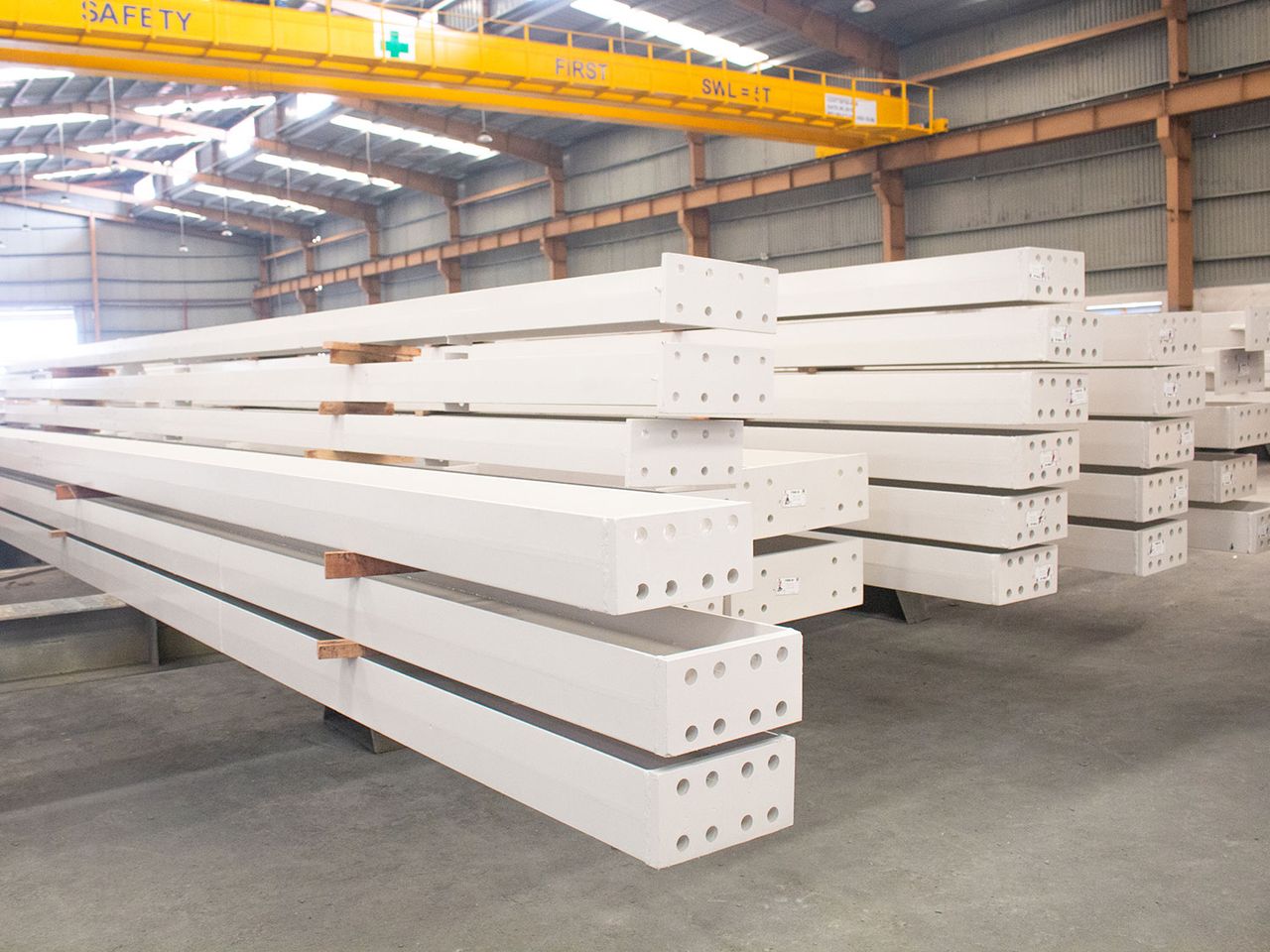
WSC cuts tapered web plates on CNC plasma or oxy-fuel tables, assembles flanges and webs on automatic lines, and welds web-to-flange fillets with submerged arc welding. Cap plates, knee end plates, stiffeners and girt clips are fitted to the shop drawing, then the member is shot blasted and primed or painted to the specified system, or hot-dip galvanised where required. The plant works to AS/NZS 5131 CC3 and EN 1090-2 EXC3 quality systems and holds IAS AC472 accreditation for metal building systems.
On site, columns are lifted onto the anchor bolts, levelled on shims or leveling nuts, temporarily guyed or braced, and connected to the rafters before the first braced bay is plumbed. Grout under the base plate is placed after the frame is aligned.
Common mistakes and quality checks
- Anchor bolt group rotated or offset so the column cannot be plumbed – check bolt positions against the anchor bolt plan before steel arrives.
- Missing or wrongly oriented flange-brace and girt clips – verify against the erection drawings at the shop final inspection.
- Flange splice welds not inspected – require UT or the specified NDT for full-penetration splices.
- Coating damage at lifting points – touch up after erection.
- Releasing temporary bracing before roof and wall bracing is complete – a frequent cause of erection failures.
Normes par région
| Région | Norme | Périmètre |
|---|---|---|
 United States |
AISC 360-22 / ASCE 7-22 | Member design and loads; MBMA Metal Building Systems Manual guidance |
 Canada |
CSA S16-19 / NBC 2020 | Limit states design of steel structures and loads |
 Australia / NZ |
AS 4100:2020 / AS/NZS 1170 | Steel structures and structural design actions |
 Europe |
EN 1993-1-1 | Eurocode 3 – general rules for steel buildings |
| International | AS/NZS 5131 / EN 1090-2 | Fabrication and execution of structural steelwork |
Questions fréquentes
Why are PEB columns tapered?
With a pinned base the bending moment is near zero at the floor and greatest at the knee, so a tapered web places steel only where the moment needs it, saving weight compared with a constant hot-rolled section.
When should a fixed column base be used?
Fixed bases are used where drift must be tightly controlled, for example in crane buildings, very tall eaves or buildings with brittle cladding. They reduce frame weight but require larger footings designed for moment.
Do rigid frame columns resist wind along the building length?
No. Columns resist transverse loads by frame action. Longitudinal wind and seismic forces are carried by rod, cable or portal bracing in the braced bays.