 ENEnglish
 VITiếng Việt
 ZH中文
 KO한국어
 JA日本語
 FRFrançais
 ITItaliano
 PTPortuguês
 ESEspañol
 HEעברית
 ARالعربية

Connections in a pre-engineered building
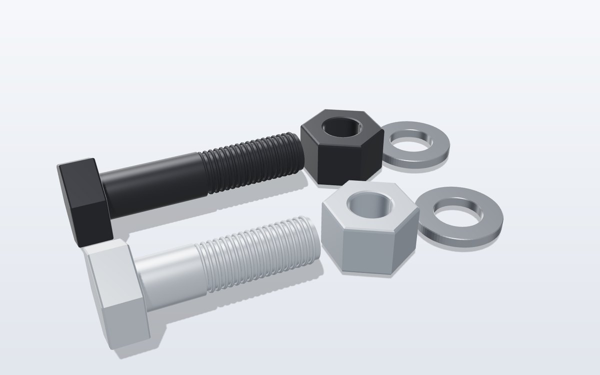
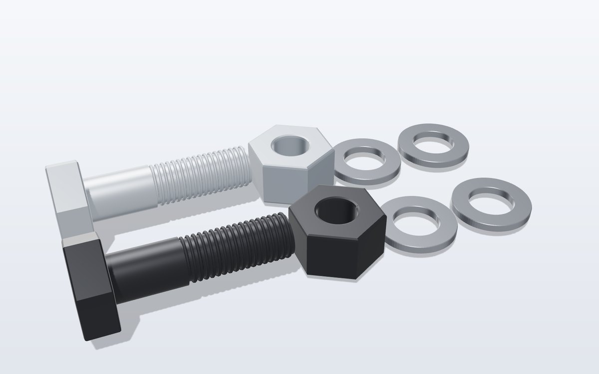
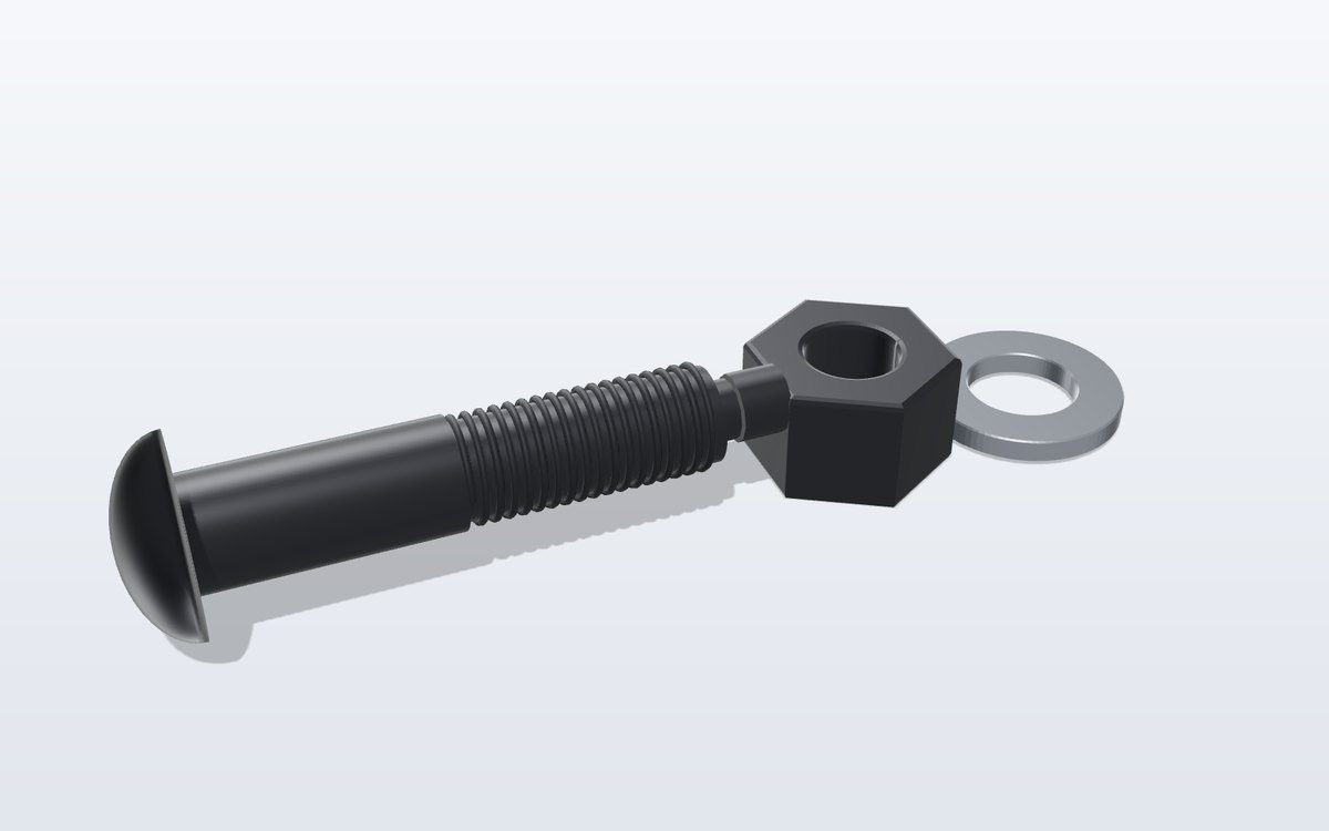
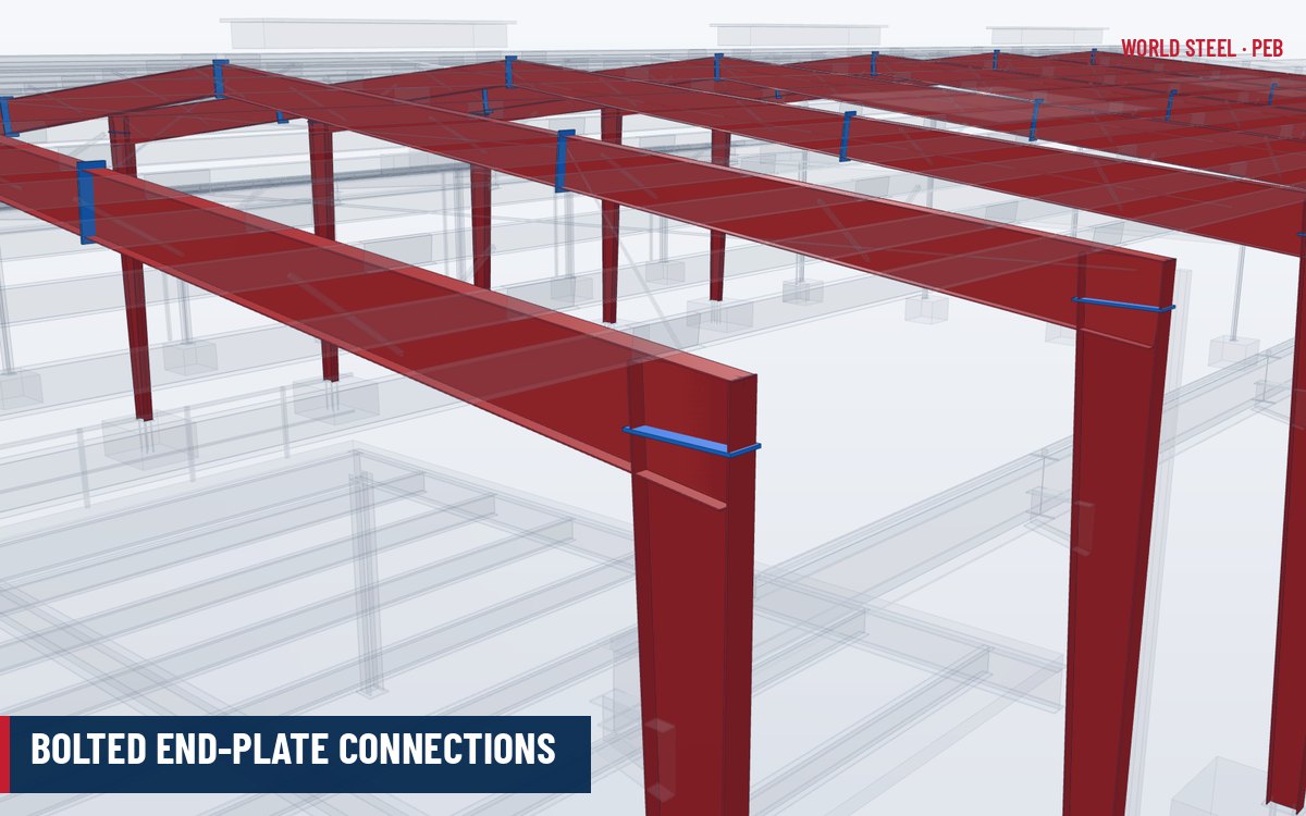
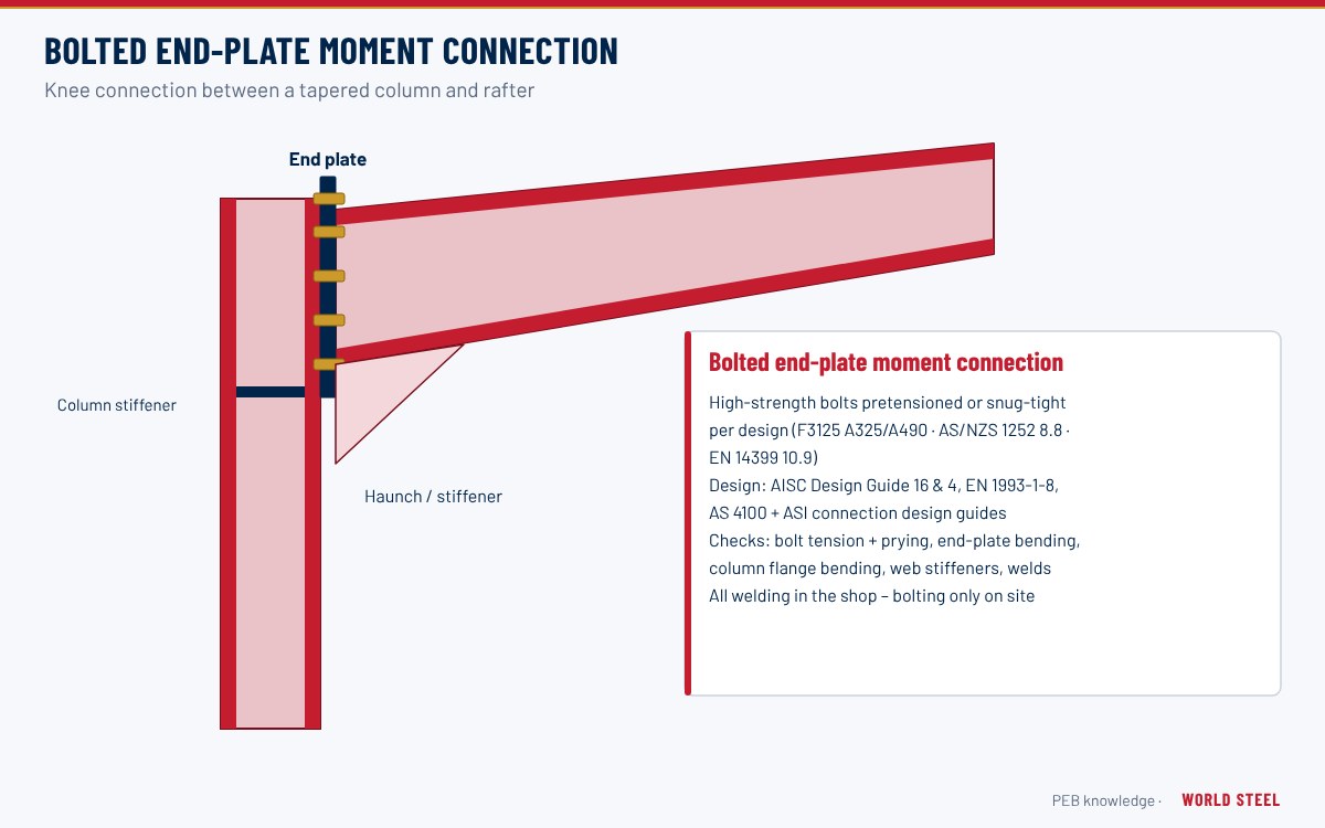
A defining feature of the PEB system is that all field connections are bolted. Members are fully welded in the factory – plates, stiffeners, clips and end plates – and on site they are joined with high-strength bolts. This makes erection fast and quality controllable, but places responsibility on connection design: connections are where load paths change direction and where most structural failures in light steel buildings originate. The main connection types are:
- Knee (column–rafter) and ridge connections: moment-resisting bolted end-plate connections.
- Rafter splices: flush or extended end plates at transport-length breaks.
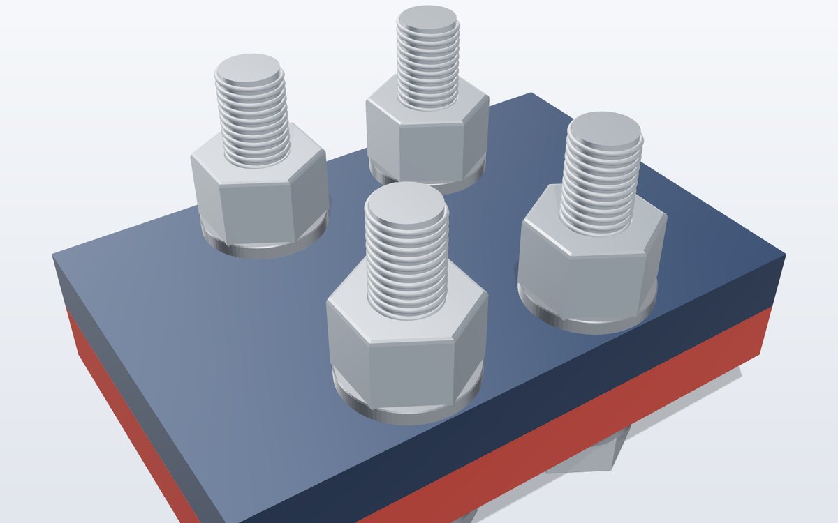
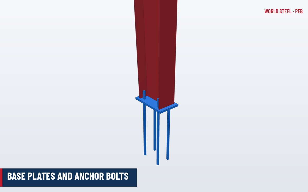
- Column bases: pinned or fixed base plates and anchor bolts.
- Bracing connections: rod or angle bracing to frames via gusset plates, hillside washers or clips.
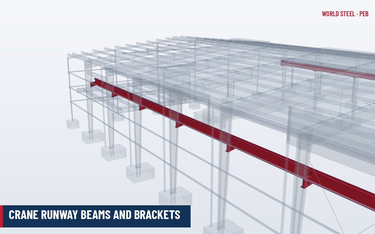
- Secondary connections: purlin and girt clips, flange braces, eave struts, crane brackets.
End-plate moment connection design
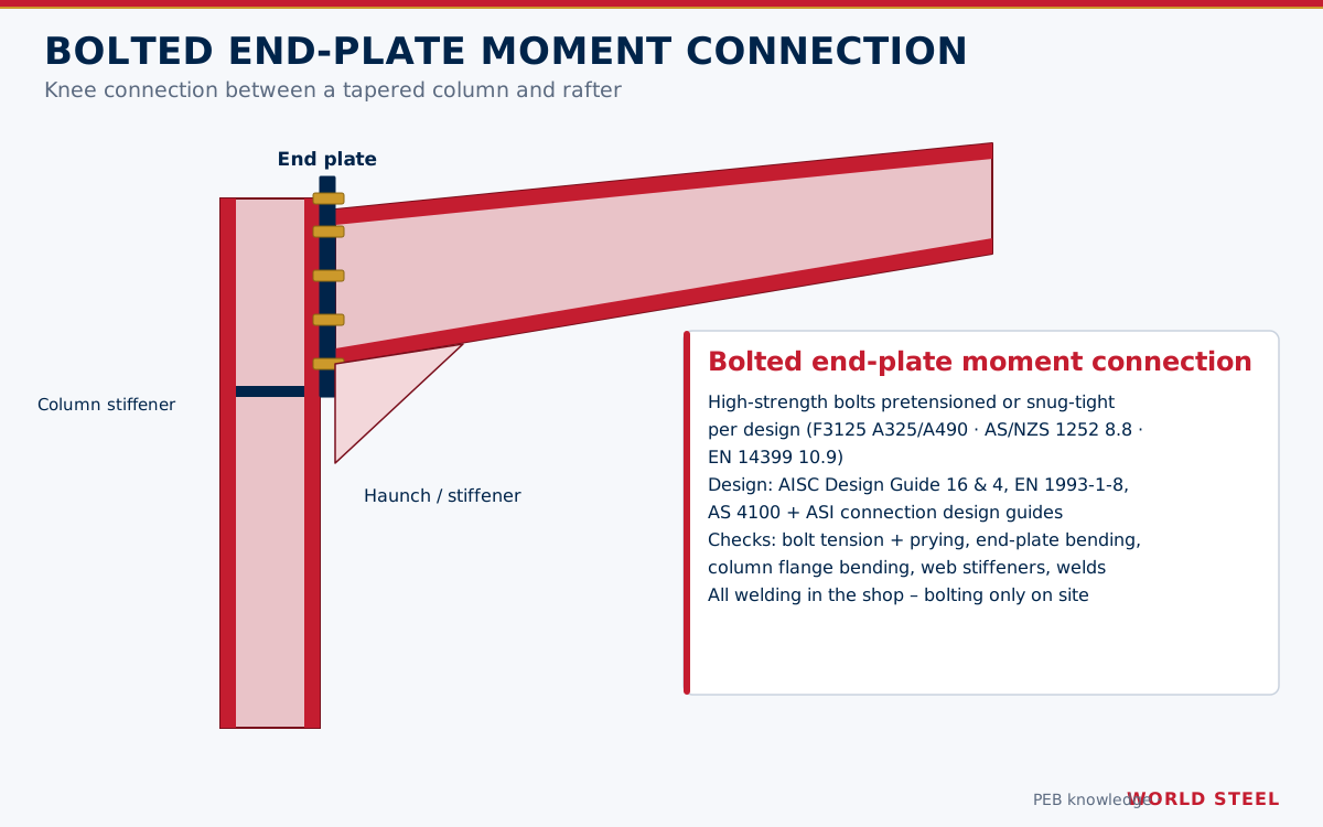
End-plate connections are designed for moment, shear and axial force. Design checks include bolt tension (with prying), end-plate bending using yield-line analysis, column flange bending and web yielding, stiffener requirements, panel-zone shear, compression-side web crippling and buckling, and weld strength between end plate and member.
| Region | Reference | Approach |
|---|---|---|
| USA | AISC 360-22 Ch. J; AISC Design Guide 39 (End-Plate Moment Connections, 2023), which consolidates the earlier Design Guides 4 and 16; AISC 358 for prequalified seismic end plates | Yield-line end-plate strength, thick- and thin-plate behaviour with prying |
| Canada | CSA S16-19 Clause 13 and 21 | Limit states design; AISC guidance commonly referenced for yield-line methods |
| Australia / NZ | AS 4100:2020 Section 9; ASI connection design guides (e.g. Design Guide 10 – bolted moment end plate beam splice connections) | Limit states design with ASI design models |
| Europe | EN 1993-1-8 | Component method – T-stub model, rotational stiffness and joint classification (rigid, semi-rigid, pinned) |
In Eurocode design, joint stiffness must be compatible with the frame analysis assumption; a nominally rigid knee that is actually semi-rigid will increase frame deflection.
Practical design rules
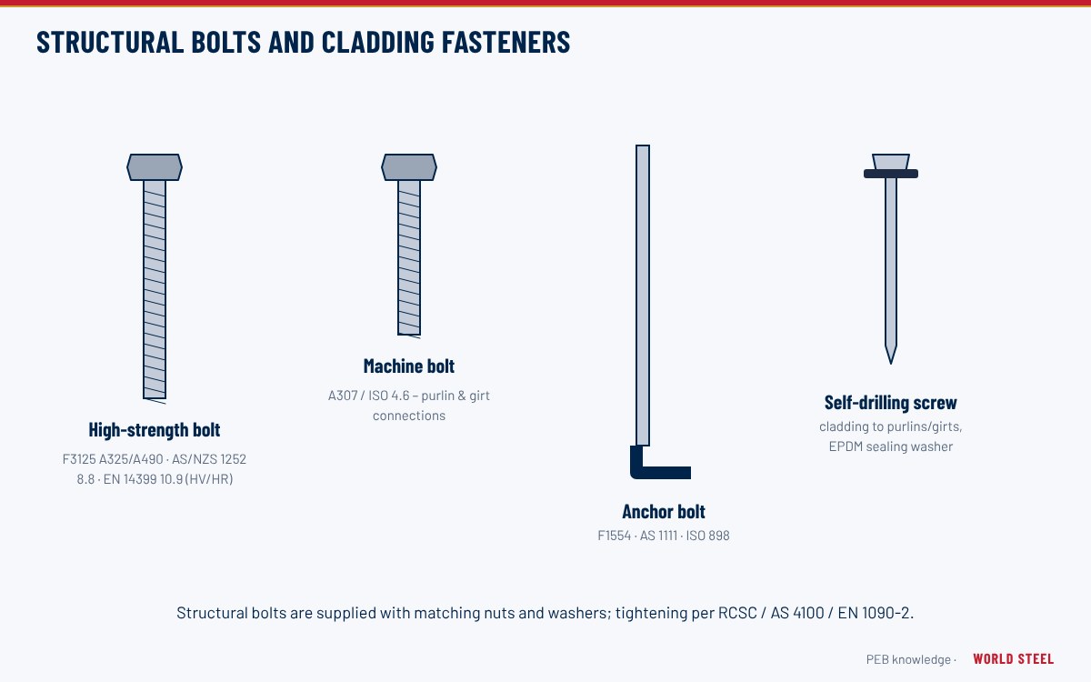
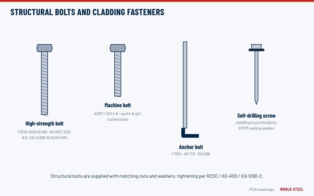
- Use pretensioned (slip-critical or "TF") bolts where load reversal, fatigue or vibration occurs, e.g. crane buildings; snug-tight or pretensioned bearing bolts elsewhere as the code allows. See structural bolts and fasteners.
- Keep end-plate thickness and bolt diameter in proportion – thin plates with large bolts cause prying; very thick plates add cost and weld distortion.
- Standardise bolt sizes (e.g. M20/M24 or 3/4 in, 7/8 in, 1 in) across a project to simplify erection.
- Check flange-to-end-plate welds for the full flange force where the connection must develop the member; CJP or matched fillet welds as designed.
- Base plates: pinned bases with two or four anchor bolts are typical for PEB; fixed bases reduce drift but increase foundation size.
- Provide erection clearances and match-marking; slotted holes only where specified.
Secondary, bracing and special connections
Beyond the moment joints, a PEB contains hundreds of lighter connections that are standardised by the supplier but still designed:
| Connection | Typical detail | Typical fasteners |
|---|---|---|
| Purlin or girt to frame | Bolted through the web to a clip welded to the rafter or column flange | M12–M16 bolts, property class 4.6 or 8.8 (A307 or A325 in US practice) |
| Purlin lap | Overlapping Z purlins bolted together over the support and at the lap ends | M12–M16 lap bolts |
| Flange brace | Angle bolted from the purlin or girt web to a plate on the frame inner flange | M12 bolts |
| Rod bracing | Rod through a hole in the web with a hillside or bevelled washer and nuts, or a forked end to a gusset | Rod threads with double nuts; tensioned at erection |
| Cable bracing | Galvanised strand with eye bolts or grip anchorage | Proprietary fittings to manufacturer's rating |
| Crane bracket | Shop-welded to the column, runway bolted on top | Pretensioned high-strength bolts |
| Mezzanine beam to column | Shear tab or end plate | Bearing or pretensioned high-strength bolts |
Clip spacing, hole positions and bolt sizes are standardised so that the cold-formed members can be punched on the roll-forming line; any change to purlin depth or girt position therefore needs to be fixed before fabrication. Uplift and longitudinal bracing forces pass through these small connections, which is why they appear on the erection drawings with the same importance as the primary bolts.
Fabrication and inspection requirements
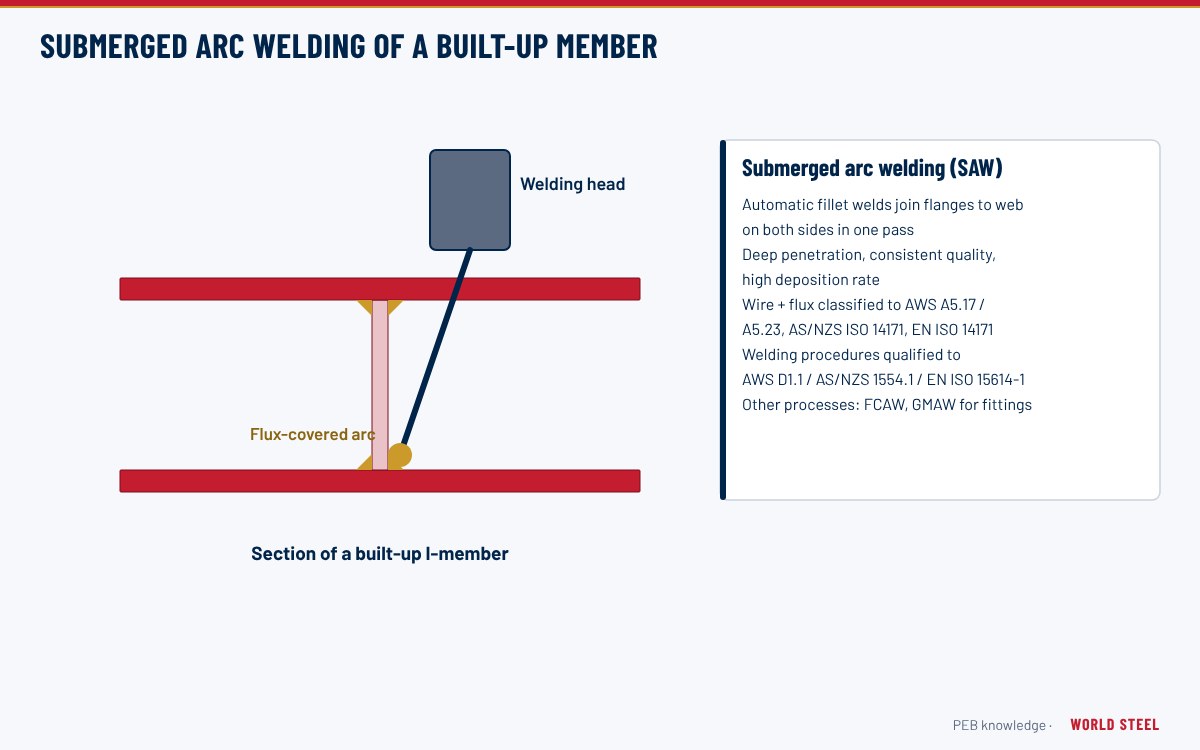
Connection welds are made under qualified procedures to AWS D1.1, AS/NZS 1554.1 or EN 1090-2 / EN ISO 3834 (see welding processes and consumables). End plates must be flat within tolerance so bolted faces bear; bolt holes are drilled or punched within code limits. Pretensioned bolts are installed and inspected by turn-of-nut, calibrated wrench, direct tension indicators or twist-off bolts per RCSC, AS 4100 / AS/NZS 5131 or EN 1090-2. World Steel fabricates to AS/NZS 5131 CC3, EN 1090-2 EXC3 and ISO 3834-2, and is accredited under IAS AC472 for metal building systems; connection design is part of its design service.
Software and documentation
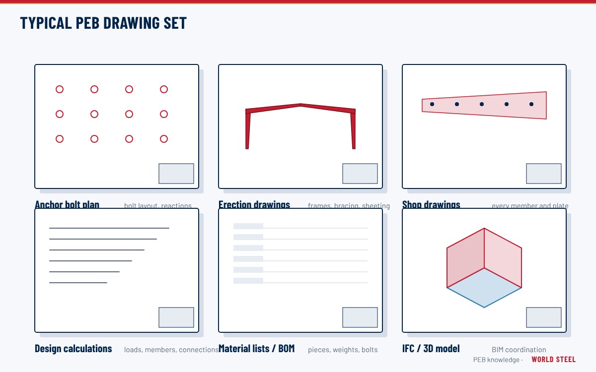
PEB connection design is commonly automated within frame design software and then verified for unusual geometries with dedicated connection software or finite-element analysis. Each connection is identified on the erection drawings with bolt size, grade, quantity and tightening method; shop drawings show plate thickness, weld sizes and hole details. These are part of the design deliverables.
Normes par région
| Région | Norme | Périmètre |
|---|---|---|
 United States |
AISC 360-22 Ch. J | Design of connections |
| United States |
AISC Design Guide 39 | End-plate moment connections |
| United States |
RCSC 2020 | Specification for structural joints using high-strength bolts |
 Canada |
CSA S16-19 | Design of steel structures – connections |
 Australia / NZ |
AS 4100:2020 Sec. 9 | Connections |
 Europe |
EN 1993-1-8 | Design of joints |
Questions fréquentes
Why are PEB frames bolted rather than site welded?
Shop welding under controlled conditions is faster and more reliable than site welding. Bolted end-plate connections let the frame be erected quickly with simple tools and consistent quality.
Which AISC design guide covers end-plate connections?
AISC Design Guide 39, published in 2023, covers end-plate moment connections and consolidates the earlier Design Guides 4 and 16. AISC 358 covers prequalified end plates for seismic moment frames.
Do all PEB bolts need to be pretensioned?
No. Pretensioning is required where the code or design calls for it, such as slip-critical joints, load reversal, fatigue or end-plate moment connections in some codes. Other connections may be snug-tight.