 ENEnglish
 VITiếng Việt
 ZH中文
 KO한국어
 JA日本語
 FRFrançais
 ITItaliano
 PTPortuguês
 ESEspañol
 HEעברית
 ARالعربية

Reading a PEB as a system
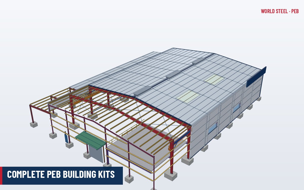
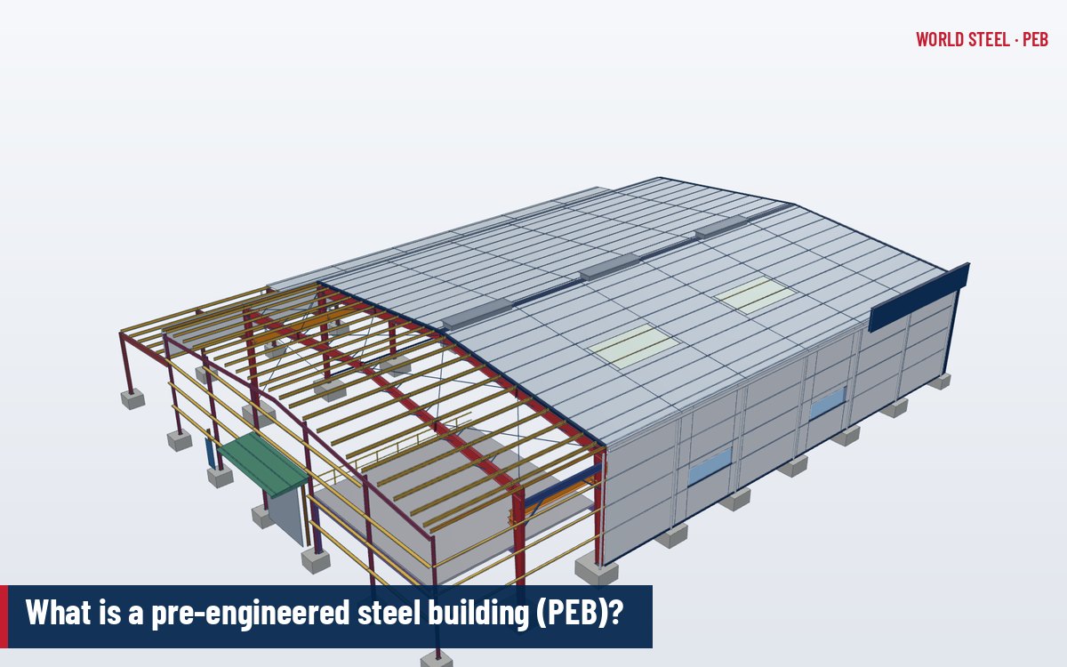
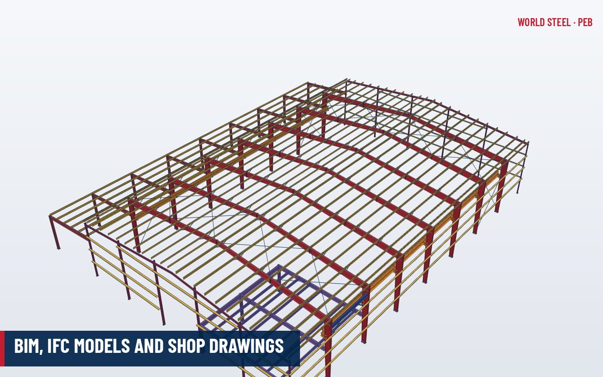
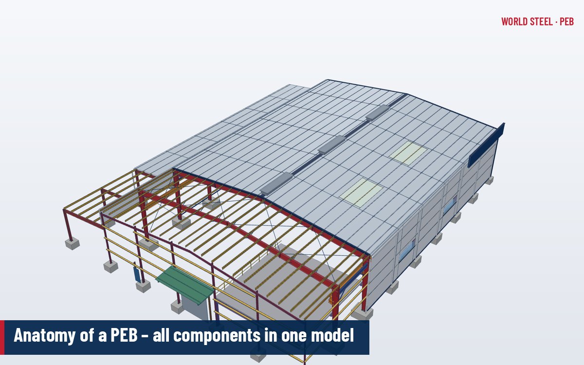
A pre-engineered steel building is made of a limited number of component families that repeat along the building length. Understanding these families – and how load passes from one to the next – makes it much easier to read a PEB quotation, a set of anchor-bolt and erection drawings, or a bill of materials. This article follows the 3D model on this page from the foundations outwards. Select a component in the model to open its own article.
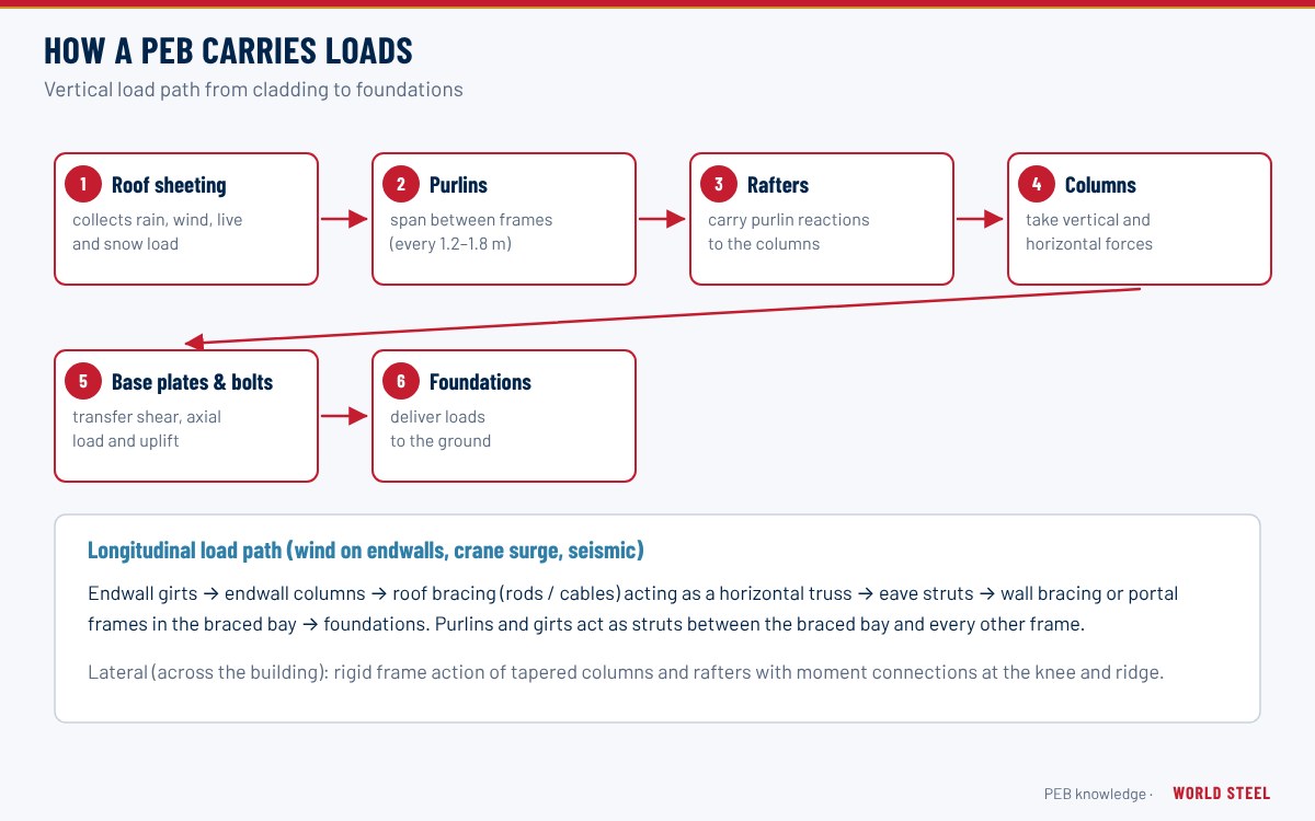
The components fall into five groups: primary framing, secondary framing, roof and wall cladding, accessories and special structures. The way loads travel through them is described in how a PEB carries loads.
| Group | Function | Typical supply form |
|---|---|---|
| Primary framing | Carries all loads to the foundations; provides the building's shape | Welded built-up members with bolted end plates |
| Secondary framing | Supports cladding, braces frames, transfers wind and longitudinal loads | Cold-formed Z/C sections, rods, cables, angles |
| Cladding | Weather-tight envelope, insulation, daylight | Profiled sheet, standing seam, sandwich panels |
| Accessories | Drainage, ventilation, access, finishing details | Formed trims, gutters, doors, louvers, ventilators |
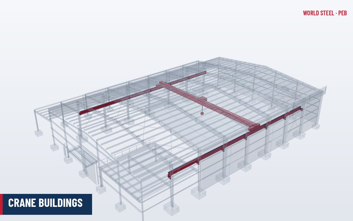
| Special structures | Cranes, mezzanines and other add-on loads | Runway beams, brackets, floor framing and deck |
Primary framing
The primary frames are the "skeleton" of the building, spaced at the bay spacing (typically 6–9 m) along its length.
- Rigid frame columns – tapered or uniform built-up columns, pinned or fixed at the base.
- Rafters – tapered roof beams joined to the columns by moment connections at the knee and ridge.
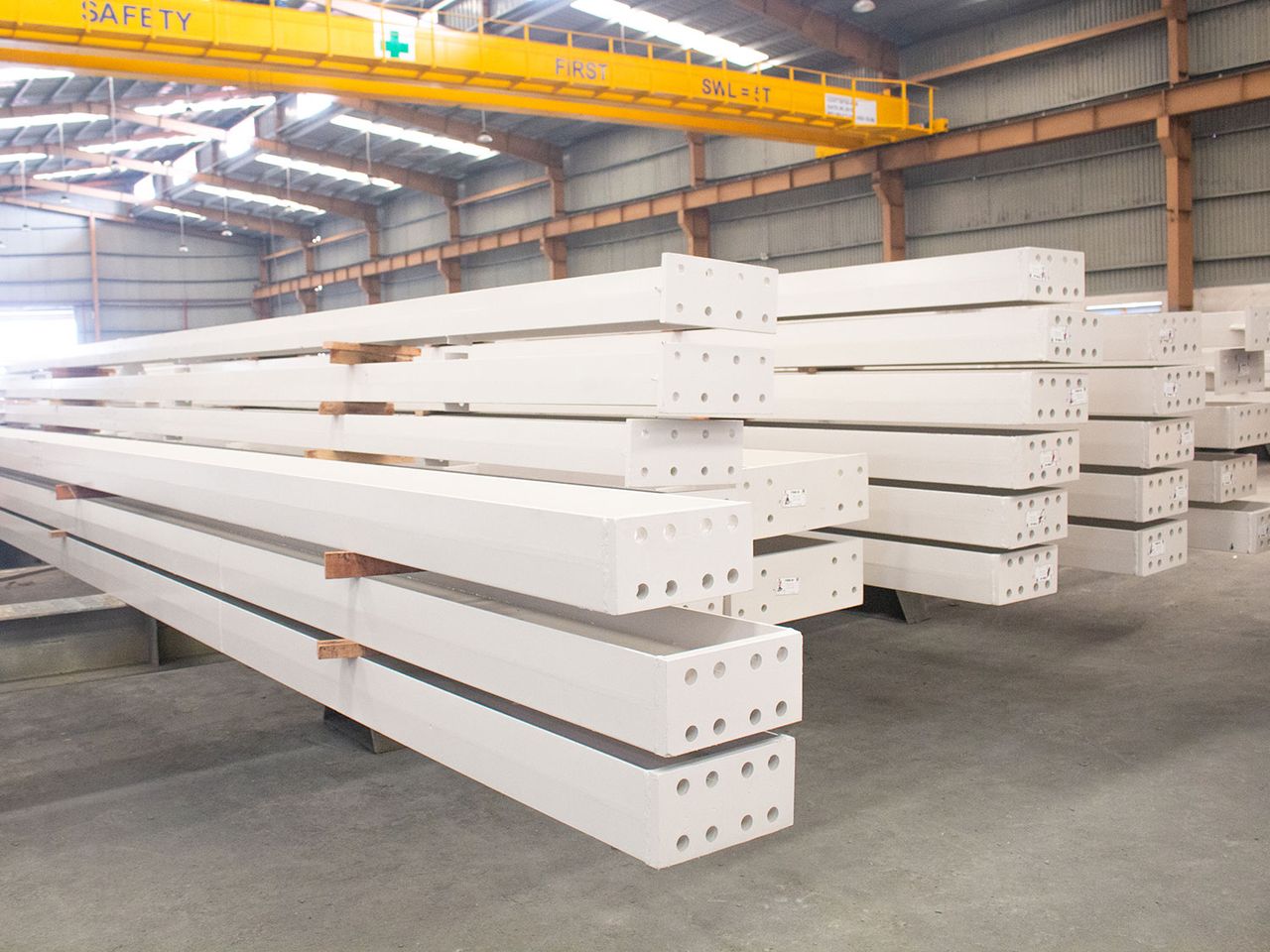
- Tapered built-up members – the welded I-sections from which columns and rafters are made.
- Endwall framing – post-and-beam or rigid endwall frames at the building ends, designed for future expansion if required.
- Bolted end-plate connections – the knee, ridge and splice joints, assembled with high-strength bolts on site.
- Base plates and anchor bolts and the foundation interface – where the steel hands its reactions to the concrete.
Secondary framing
Secondary members span between the frames and give the cladding its support.
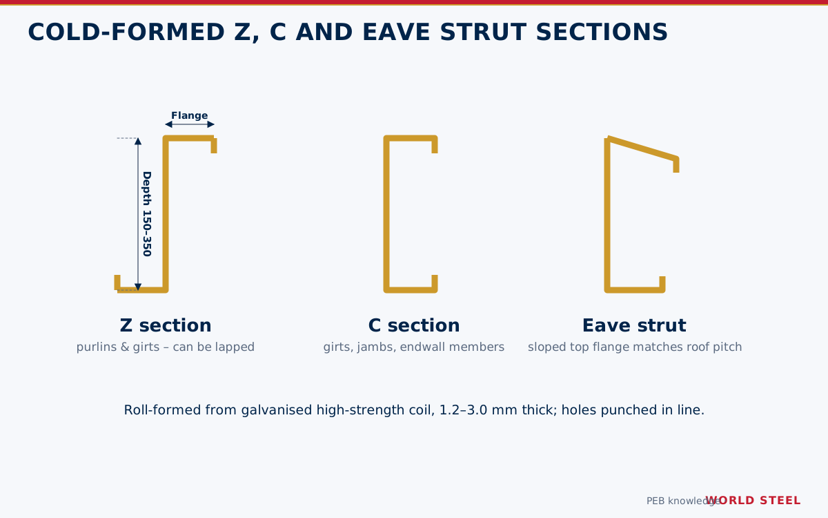
- Purlins – Z or C roof members, usually lapped over the rafters for continuity.
- Girts – horizontal wall members spanning between columns.
- Eave struts – the member at the junction of roof and wall, supporting the edges of both claddings.
- Flange braces – small angles from purlins or girts to the inner flange of the frame, controlling lateral-torsional buckling.
- Bracing systems – rod, cable and portal bracing that carry longitudinal wind and seismic loads.
- Sag rods and bridging – restraints that keep purlins and girts straight and stable.
Roof and wall cladding
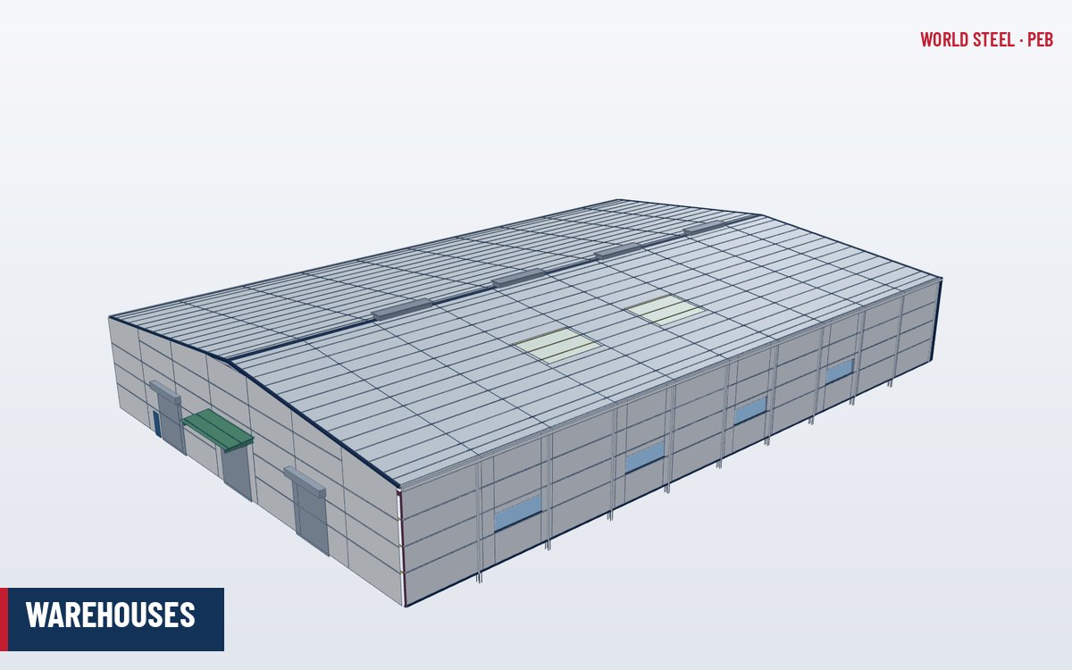
- Roof sheeting – through-fastened trapezoidal profiles, the most economical roof.
- Standing seam roofs – concealed-clip roofs for low slopes and long sheet runs.
- Wall sheeting – profiled wall cladding, often in a different profile or colour from the roof.
- Insulation – fibreglass or mineral wool blankets, reflective foil or rigid boards.
- Skylights and translucent panels – polycarbonate or GRP sheets matching the roof profile.
- Insulated sandwich panels – factory-bonded panels for cold stores and high thermal performance.
Names and abbreviations on PEB drawings
PEB erection drawings use a compact vocabulary. Frames are identified by grid lines – numbers along the length, letters across the width – and members carry piece marks that match the bill of materials. A few terms describe position rather than member type: the end bay is the bay between an endwall and the first interior frame, the braced bay is any bay carrying rod, cable or portal bracing, and an interior bay is any other bay. Girts are by-pass when they run outside the column flanges, or flush (inset) when they are framed between columns so that the wall finish aligns with the column face.
| Abbreviation | Meaning | Abbreviation | Meaning |
|---|---|---|---|
| RF | Rigid frame | EW / SW | Endwall / sidewall |
| P&B | Post-and-beam endwall | ES | Eave strut |
| CS / MS | Clear span / multi-span | LT | Lean-to |
| FFL | Finished floor level | EH | Eave height |
| AB | Anchor bolt | FO | Framed opening |
| HSB | High-strength bolt | SDS / STS | Self-drilling / self-tapping screw |
| TRC / UHC / MR | Top-running / underhung / monorail crane | NS / FS | Near side / far side |
| O/O | Out-to-out dimension | TYP | Typical (applies to all similar locations) |
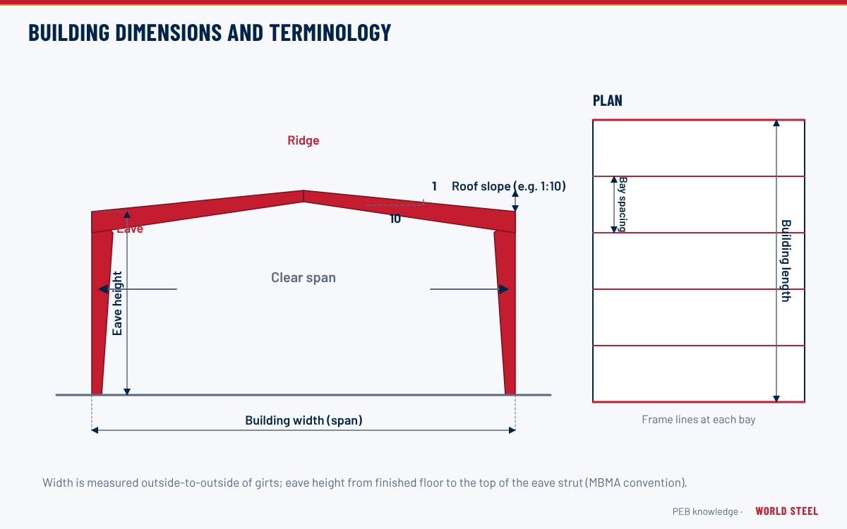
Definitions of the main dimensional terms – steel line, eave height, clear height, bay spacing and roof slope – are in building dimensions and terminology, and the full list of terms is in the PEB glossary.
Accessories and special structures
Accessories complete the envelope and make the building usable:
- Ridge ventilators and wall louvers for natural ventilation.
- Gutters and downspouts for rainwater drainage.
- Trims and flashings at corners, eaves, rakes and openings.
- Canopies, fascias and parapets for weather protection and architectural finish.
- Doors and framed openings and windows.
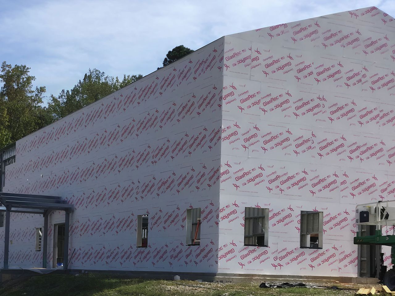
Special structures are added when the building has to carry more than its envelope: crane runway beams and brackets for overhead cranes, and mezzanine floors for offices or storage above ground level.
World Steel supplies every group shown in the model as one coordinated package, with anchor-bolt plans, erection drawings and a part-marked bill of materials – see WSC pre-engineered buildings.
Normes par région
| Région | Norme | Périmètre |
|---|---|---|
 United States |
MBMA Metal Building Systems Manual 2018 | Common industry practice and terminology |
| United States |
AISI S100-16 (2020) | Cold-formed steel design |
 Canada |
CSA S136-16 | Cold-formed steel structural members |
 Australia / NZ |
AS/NZS 4600:2018 | Cold-formed steel structures |
 Europe |
EN 1090-4 | Execution of cold-formed elements for roof, floor and wall applications |
Questions fréquentes
What is the difference between primary and secondary framing?
Primary framing is the rigid frames (columns and rafters) that carry the building's loads to the foundations. Secondary framing is the lighter cold-formed purlins, girts and eave struts that support the cladding and brace the primary frames.
Are foundations part of the PEB supply?
Normally not. The PEB supplier provides anchor-bolt layouts and column reactions; the foundations are designed and built by others. Anchor bolts may be supplied with the steel package on request.
Which components are most often added as options?
Insulation, skylights, ridge ventilators, louvers, canopies, mezzanine floors and crane runways are the most common options. Each must be specified before design, because it changes loads on the frames.
What is a braced bay?
A braced bay is a bay that contains the diagonal roof and wall bracing (or a portal frame) that carries longitudinal wind, seismic and crane forces to the foundations. Its location is shown on the erection drawings and it must not be altered without engineering review.