 ENEnglish
 VITiếng Việt
 ZH中文
 KO한국어
 JA日本語
 FRFrançais
 ITItaliano
 PTPortuguês
 ESEspañol
 HEעברית
 ARالعربية

What the service covers
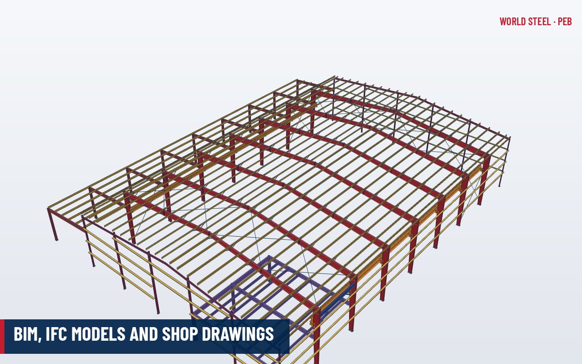
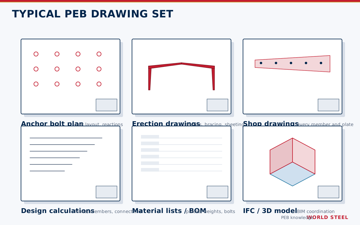
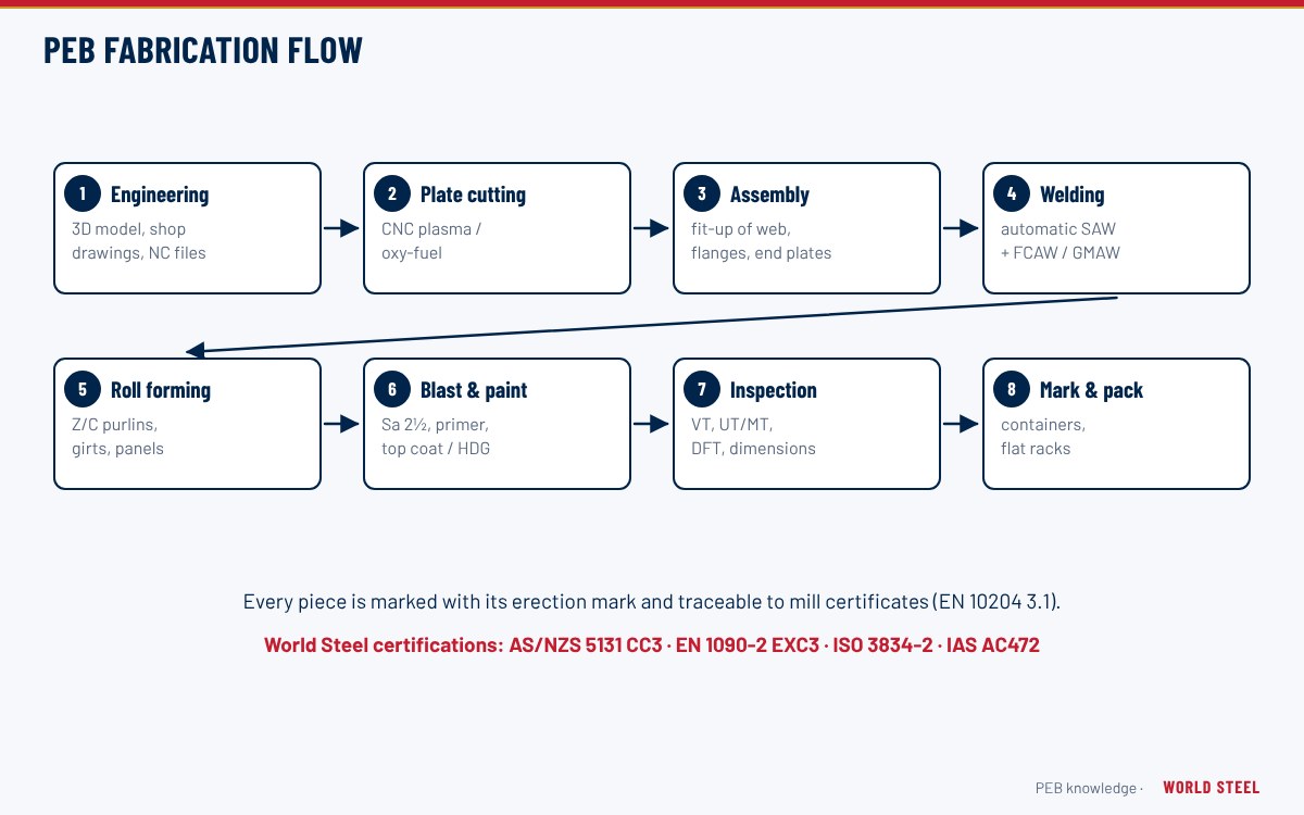
Detailing turns a design into instructions for the shop and the site. World Steel models every building in 3D, produces drawings and CNC data from the model, and exports an open IFC model so that owners, architects and contractors can check the steel in their own BIM tools. The service is part of the design solution. Steps:
- Model the structure from the approved design: members, plates, bolts, holes and welds.
- Clash and constructability checks, including coordination with architectural or MEP models supplied by the client.
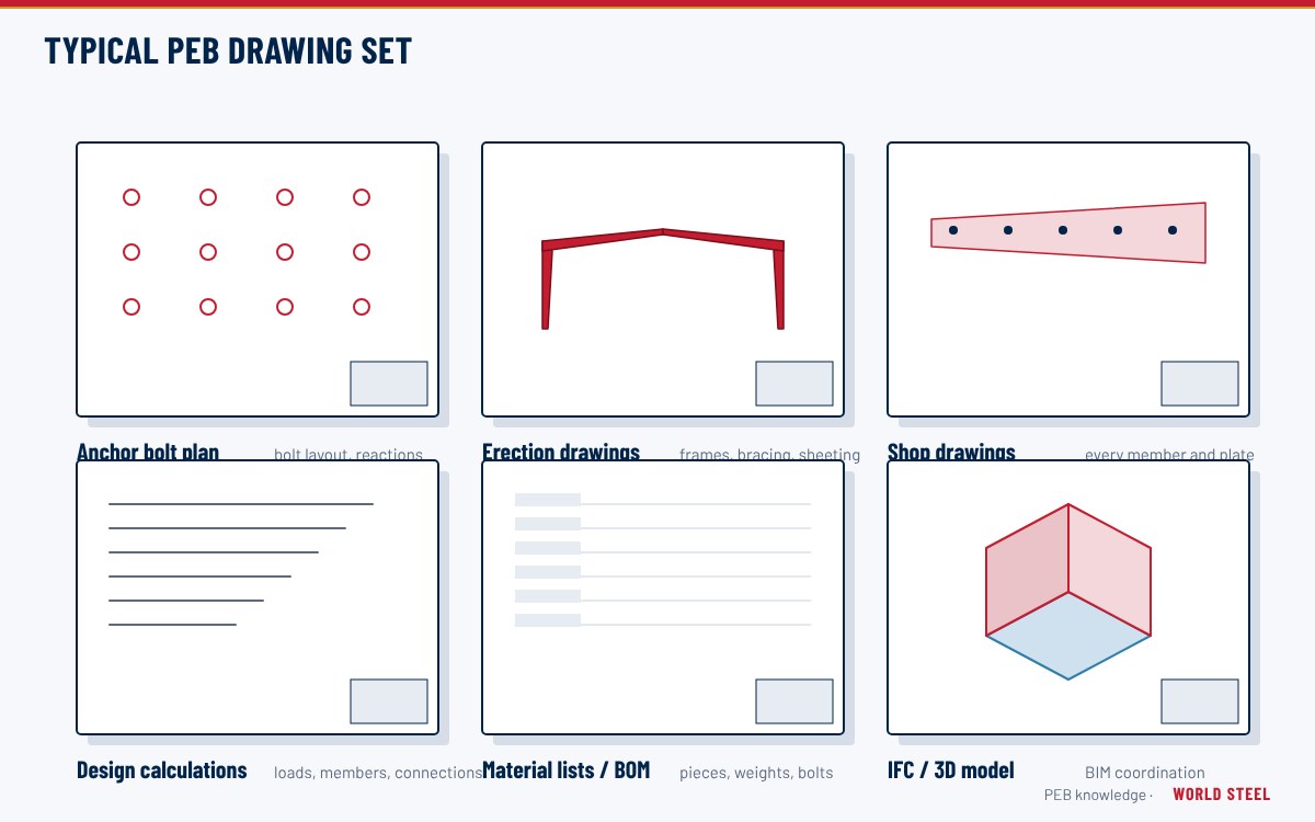
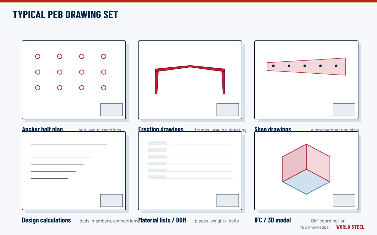
- Generate approval drawings and, after approval, shop drawings (assembly and single-part) and erection drawings.
- Export NC data (for example DSTV format) to CNC cutting, drilling and roll-forming machines.
- Export IFC (ISO 16739-1) and, on request, native or PDF formats, with piece marks matching the physical parts.
Inputs needed from the client
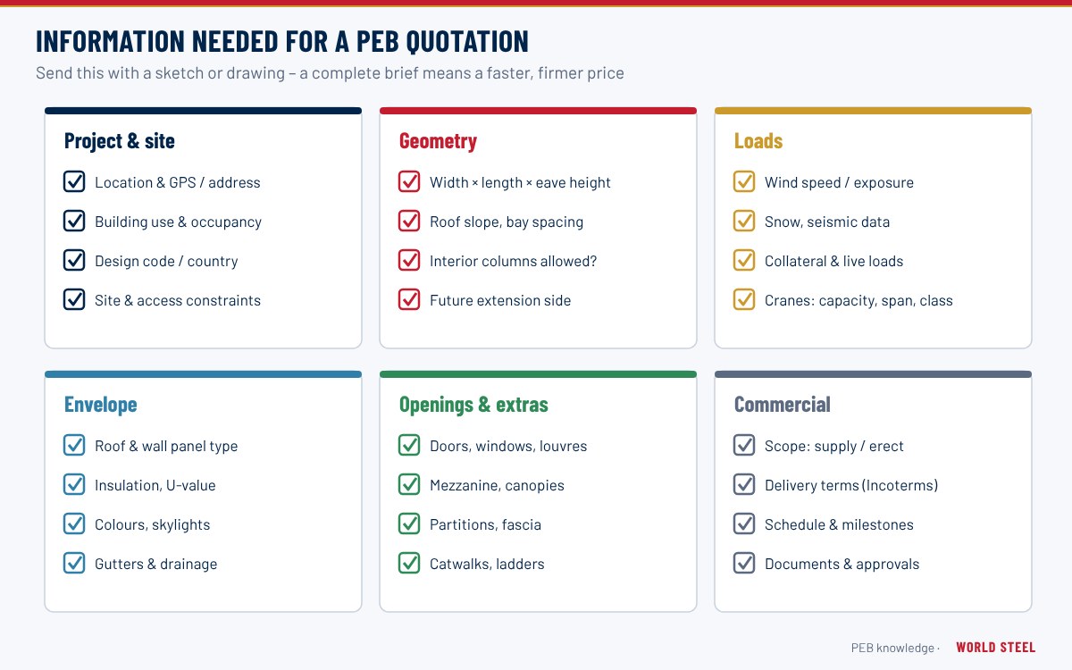
- Approved design drawings and calculations, or WSC design.
- Architectural grid, levels and any reference models (IFC preferred).
- Required level of detail and model property sets (for example piece mark, weight, profile, grade, finish).
- Drawing standards, title blocks, units and language requirements.
- Review process and turnaround times for comments.
Deliverables
| Deliverable | Format | Use |
|---|---|---|
| Approval drawings | Client and engineer review | |
| Shop drawings (assembly and part) | Fabrication and inspection | |
| Erection drawings and bolt lists | PDF / XLSX | Site erection |
| NC files | DSTV / machine formats | CNC cutting and drilling |
| 3D model | IFC (ISO 16739-1) | Coordination, clash detection, viewing |
| Material and weight reports | XLSX | Procurement, logistics, costing |
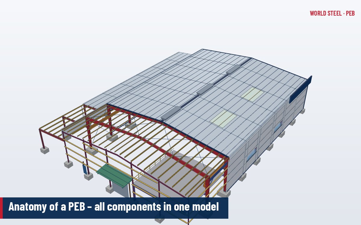
Models can be viewed on the World Steel portfolio site in the 3D viewer, the same way the building on the anatomy of a PEB page is shown.
Quality and compliance
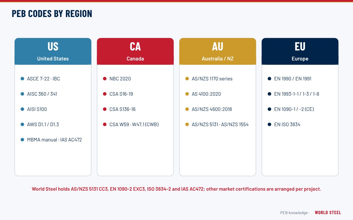
Drawings are checked by a second detailer before release, and every revision is tracked in a drawing register. Detailing conventions follow the market: AISC detailing practice and US customary or metric units for the United States, CISC practice for Canada, AS/NZS 5131 documentation requirements for Australia and New Zealand, and EN 1090-2 execution specification requirements for Germany, the United Kingdom and the rest of Europe. Piece marks, weld symbols (AWS A2.4 or ISO 2553) and bolt designations follow the code of the job. See design deliverables.
Using the IFC model
An IFC model is most useful when it is shared early. Owners and architects use it to check clear heights, door and crane clearances and roof drainage; MEP designers use it to route ducts and pipes around rafters and bracing; and contractors use it to plan cranes and lifts. Because each member carries its piece mark, weight and grade, the model also supports logistics planning and site receipt. The model shows the steel as fabricated, so the agreed revision should be used for coordination, and any change requested after release of shop drawings goes back through the drawing register and the design check.
Envelope and accessories in the model. Structural members are modelled piece by piece, while the envelope is usually represented in a lighter way that still supports coordination and quantity take-off:
| Item | Typical representation |
|---|---|
| Roof and wall sheets | Sheet layout with lengths and profiles; detailed in drawings and schedules |
| Trims and flashings | Marked on drawings with cross-section details and a trim schedule |
| Doors, windows, louvers, ventilators | Openings and framing modelled; product as a simple solid with attributes |
| Crane runway and mezzanine | Fully modelled like primary steel |
| Sundries and fasteners | Quantities in bolt and fastener lists rather than as model objects |
See design deliverables, roof sheeting and trims and flashings for how these items are documented.
Typical schedule
Typically, approval drawings for a single-storey PEB are issued about 1–3 weeks after order, and shop drawings about 1–3 weeks after approval, overlapping with material procurement. Large or highly coordinated BIM projects take longer, and review turnaround by the client affects the programme. These ranges are indicative.
地域別の規格
| 地域 | 規格 | 範囲 |
|---|---|---|
| International | ISO 16739-1 | Industry Foundation Classes (IFC) for data sharing |
 United States |
AWS A2.4 | Standard symbols for welding, brazing and NDE |
| United States |
AISC 303 | Code of standard practice – drawings and approvals |
 Australia / NZ |
AS/NZS 5131 | Documentation requirements |
 Europe |
EN 1090-2 | Execution specification and documentation |
| International | ISO 2553 | Welding symbols |
よくある質問
Can WSC deliver an IFC model?
Yes. An IFC model of the steel structure with piece marks and properties is available on request for coordination and viewing.
Can WSC detail to another engineer's design?
Yes. Shop drawings can be prepared from the client's design drawings and submitted to the engineer for approval.
Which weld symbol standard is used?
AWS A2.4 for North American projects and ISO 2553 for Europe and most other markets, as specified.
 Germany