 ENEnglish
 VITiếng Việt
 ZH中文
 KO한국어
 JA日本語
 FRFrançais
 ITItaliano
 PTPortuguês
 ESEspañol
 HEעברית
 ARالعربية

What a tapered built-up member is
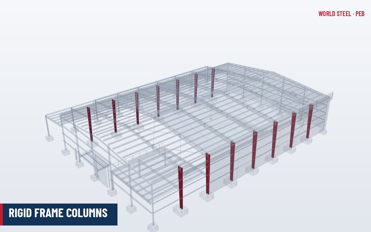
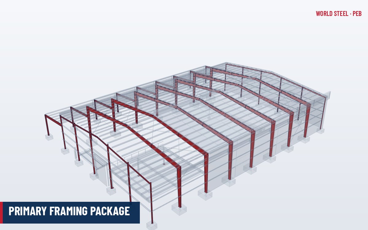
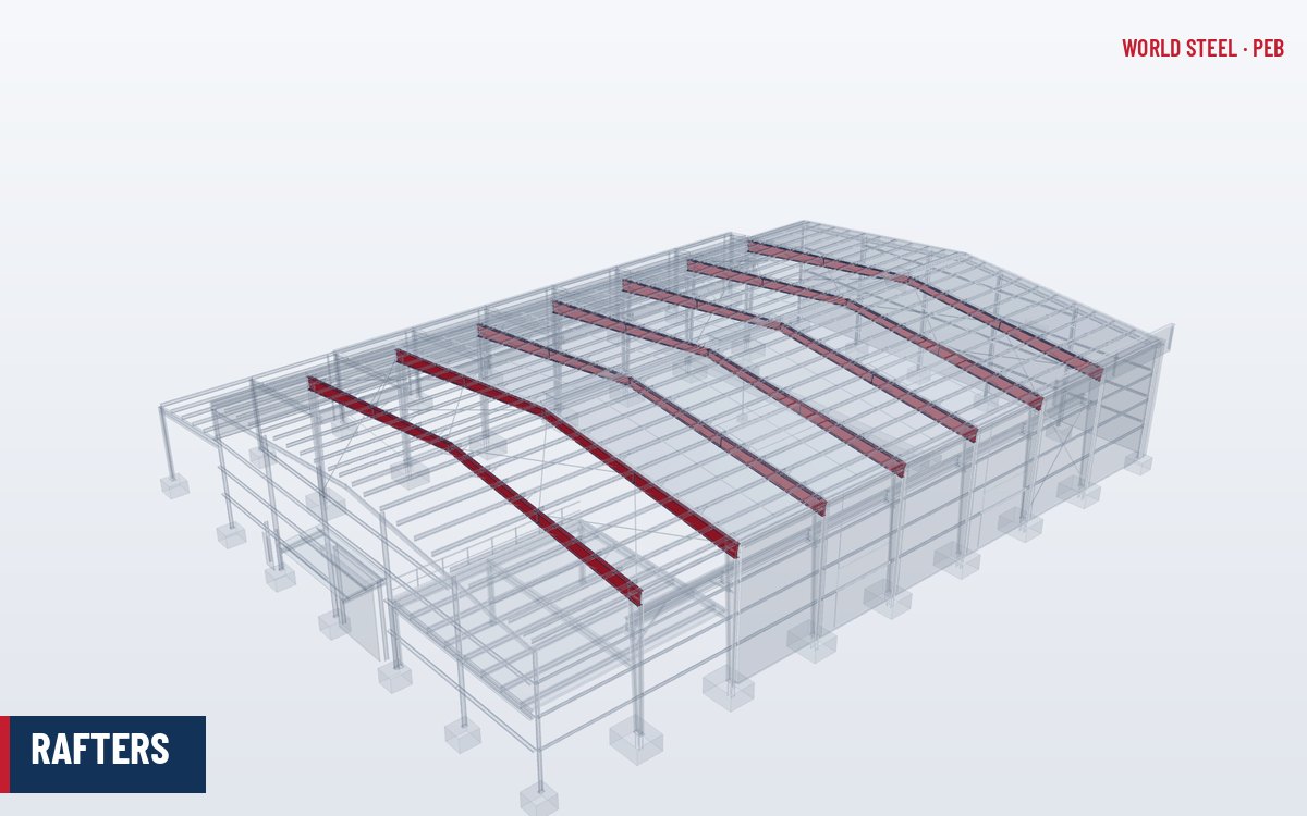
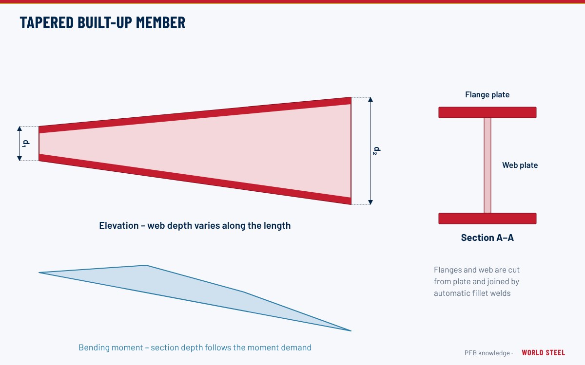
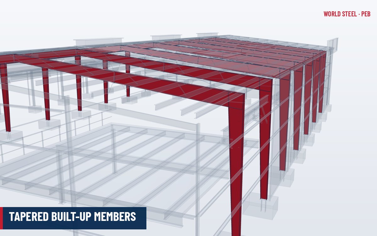
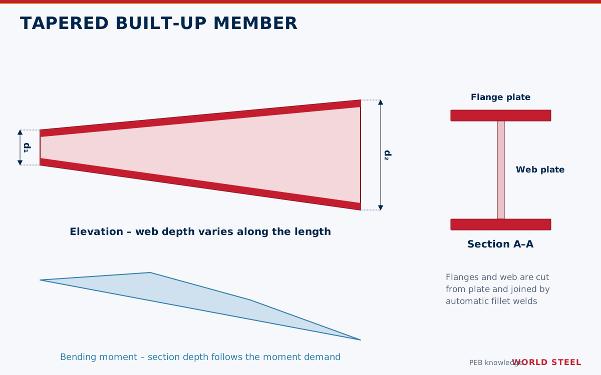
A tapered built-up member is an I-section welded from three steel plates – two flanges and a web – in which the web depth varies linearly along the length. It is the defining element of a pre-engineered building: rigid frame columns and rafters are made this way so that the section follows the bending moment diagram of the portal frame.
Compared with a frame of constant hot-rolled sections, a tapered frame uses steel only where the moment requires it. Flange width and thickness can also change between segments, so a single member may have several web tapers and flange plates joined by full-penetration shop splices.
Role in the load path
Tapered members form the primary frame that carries all transverse loads – roof gravity, wind and seismic – from the secondary members to the foundations. Their efficiency depends on stability: the deep, slender web is stiffened by its flanges and by end plates, and the compression flange is restrained by flange braces and the secondary framing. Without those restraints the efficient section loses most of its capacity.
Typical plate sizes and materials
| Element | Typical range | Comment |
|---|---|---|
| Web depth | 200–1,800 mm | Linear taper; several segments per member |
| Web thickness | 4–12 mm | Thin webs; shear checked including tension-field rules where permitted |
| Flange width | 150–450 mm | Limited by local buckling width-thickness ratio |
| Flange thickness | 6–30 mm | Changed by splices to follow the moment |
| Member length per piece | Up to ~12 m (container), longer on flat racks | Set by transport |
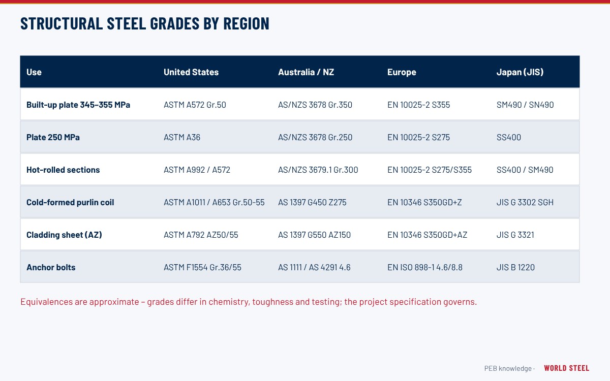
| Region | Standard | Typical grade |
|---|---|---|
| US / Canada | ASTM A572 / A1011 / CSA G40.21 | Gr 50 / HSLAS Gr 50 / 350W |
| Australia / NZ | AS/NZS 3678 | Grade 300 or 350 |
| Europe | EN 10025-2 | S275 or S355 |
See structural steel plate grades for toughness requirements and mill certificate content.
Design considerations
- Web slenderness: AISC 360-22 limits unstiffened webs to h/tw ≤ 260; EN 1993-1-5 and AS 4100 have equivalent limits and plate buckling rules.
- Flange local buckling: compact or non-compact flange classification limits flange width for a given thickness.
- Lateral-torsional buckling of tapered segments: treated in AISC Design Guide 25 (Frame Design Using Web-Tapered Members), EN 1993-1-1 general method or advanced analysis.
- Taper angle: large flange slopes induce web stresses at the bends; most designs keep tapers moderate.
- Seismic regions: AISC 341 or CSA S16 clause 27 may require stricter width-thickness limits and protected zones.
| Item | Purpose | Where it is typically found |
|---|---|---|
| Bearing (load-carrying) stiffeners | Prevent web crippling and yielding under concentrated loads | Knee, under crane brackets, interior column caps, jack-beam seats |
| Transverse shear stiffeners | Increase shear buckling capacity of slender webs | Near the knee and at high-shear zones of long rafters |
| Diagonal (panel-zone) stiffeners | Carry panel-zone shear at the knee | Column-rafter connection of deep or heavily loaded frames |
| End plates and cap plates | Bolted moment or shear connection; close the member end | Knee, ridge, splices, column tops |
| Clips and flange-brace plates | Connect purlins, girts and flange braces | Along the flanges at the secondary member spacing |
Single-sided web-to-flange fillet welds are common in metal building practice where the design shows them to be adequate, but they are not appropriate everywhere: zones with concentrated loads, fatigue from cranes, or seismic detailing requirements usually need double-sided welds, and some codes and specifications restrict one-sided fillets subject to bending about the weld root.
Fabrication and coating
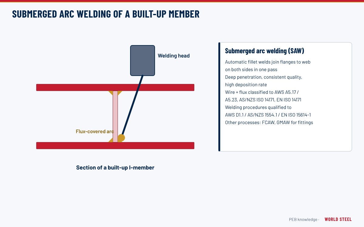
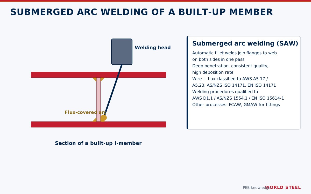
World Steel builds tapered members on a dedicated line, outlined in automatic welding of built-up members:
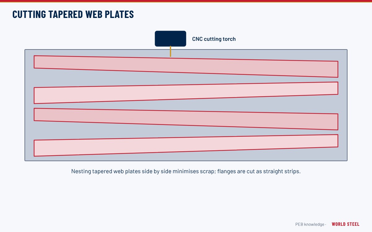
- Web plates nested and CNC-cut from wide plate, with the taper cut along the plate (see plate cutting and web tapering).
- Flange strips slit and spliced to length with full-penetration butt welds and NDT.
- H-beam assembly machine tacks flanges to web.
- Web-to-flange fillet welds by submerged arc welding – single-sided fillets are common in PEB practice where the design permits.
- Straightening of flange distortion, fitting of end plates and stiffeners, drilling of bolt holes.
- Shot blasting to ISO 8501-1 Sa 2½ (or as specified) and painting, or hot-dip galvanising.
Quality checks and common mistakes
- Dimensional checks of depth at both ends, flange tilt, web out-of-flatness and sweep against AS/NZS 5131, EN 1090-2 or AWS D1.1 and the AISC Code of Standard Practice.
- Weld size and profile on web-to-flange fillets; NDT on flange and web butt splices.
- Single-sided web fillets on members whose design assumes double-sided welds – the weld detail on the shop drawing must match the design.
- Thin webs dented in handling – use proper dunnage and slings.
WSC works under ISO 3834-2 welding quality requirements and fabricates to AS/NZS 5131 CC3 and EN 1090-2 EXC3 where specified.
地域別の規格
| 地域 | 規格 | 範囲 |
|---|---|---|
 United States |
AISC 360-22 / AWS D1.1 | Design of nonprismatic members (with AISC DG 25) and structural welding |
 Canada |
CSA S16-19 / CSA W59 | Design and welded steel construction |
 Australia / NZ |
AS 4100:2020 / AS/NZS 1554.1 | Design and structural welding |
 Europe |
EN 1993-1-1 / EN 1993-1-5 | General rules and plated structural elements |
| International | ISO 3834-2 | Comprehensive quality requirements for fusion welding |
よくある質問
Are tapered members weaker than hot-rolled sections?
No. They are designed to the same codes and are often more efficient, but they rely on proper flange bracing and careful welding to reach their capacity.
Are single-sided web-to-flange welds acceptable?
Single-sided fillet welds are widely used in metal building frames where the design checks show they are adequate. The detail must be specified by the engineer and shown on the shop drawings.
How much steel does tapering save?
Savings depend on span, loads and code; tapering typically reduces primary frame weight compared with constant sections, but the exact figure must come from a project design comparison.