 ENEnglish
 VITiếng Việt
 ZH中文
 KO한국어
 JA日本語
 FRFrançais
 ITItaliano
 PTPortuguês
 ESEspañol
 HEעברית
 ARالعربية

Definition and function
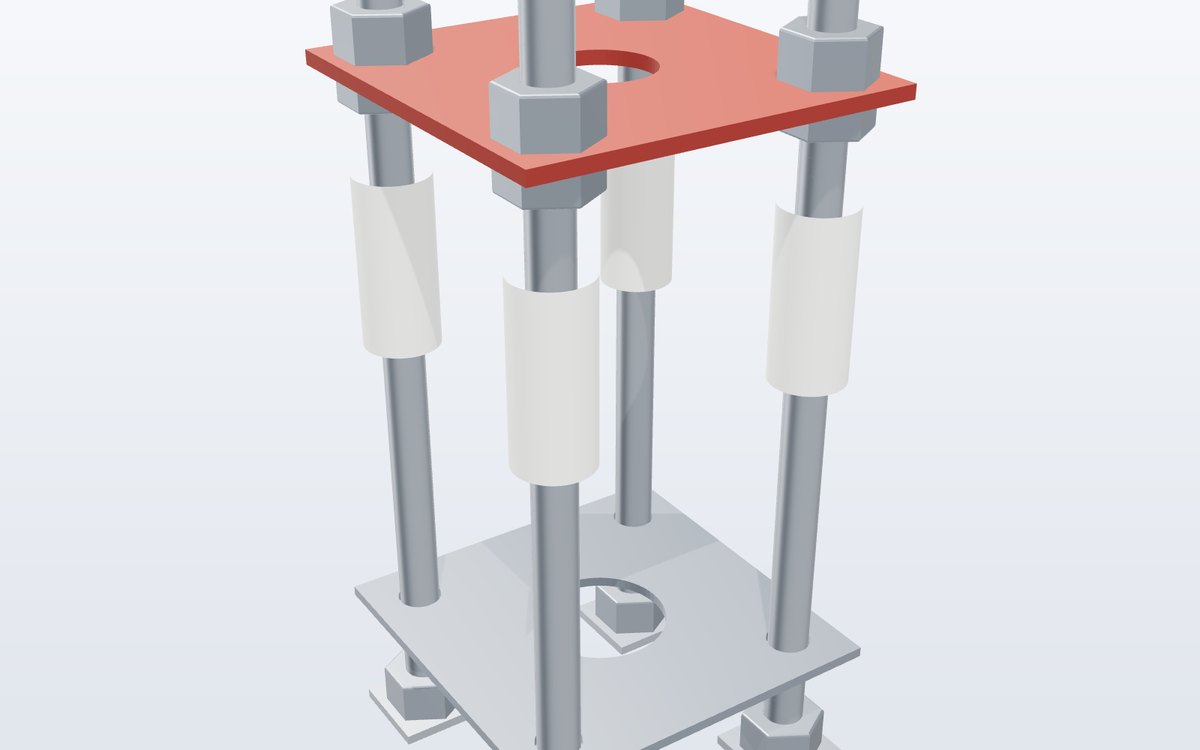
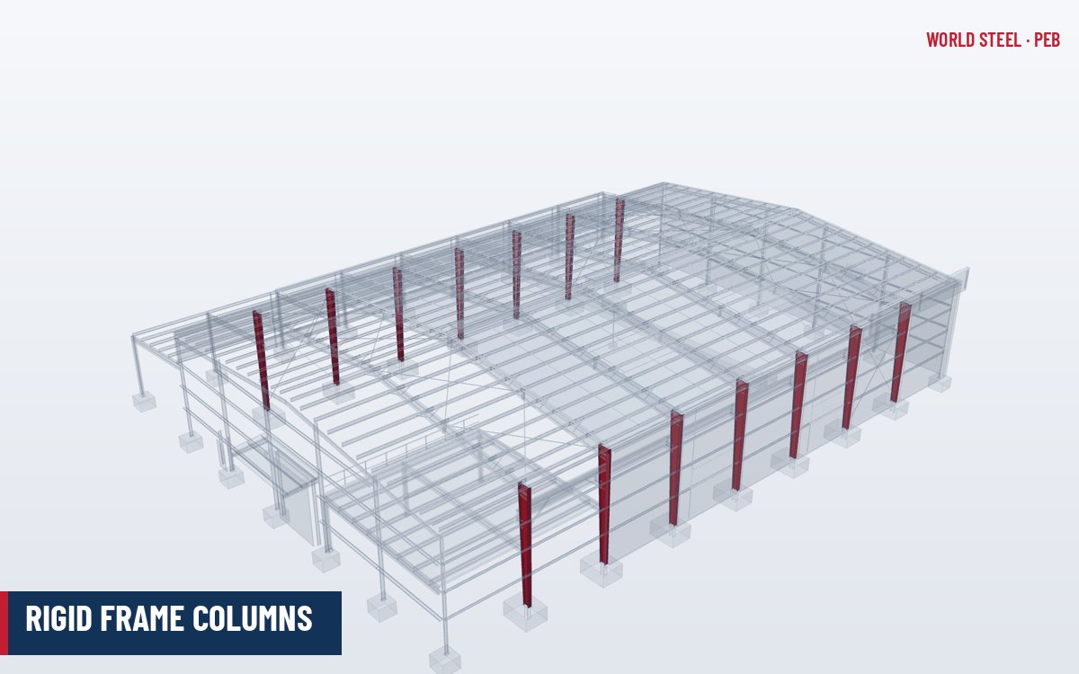
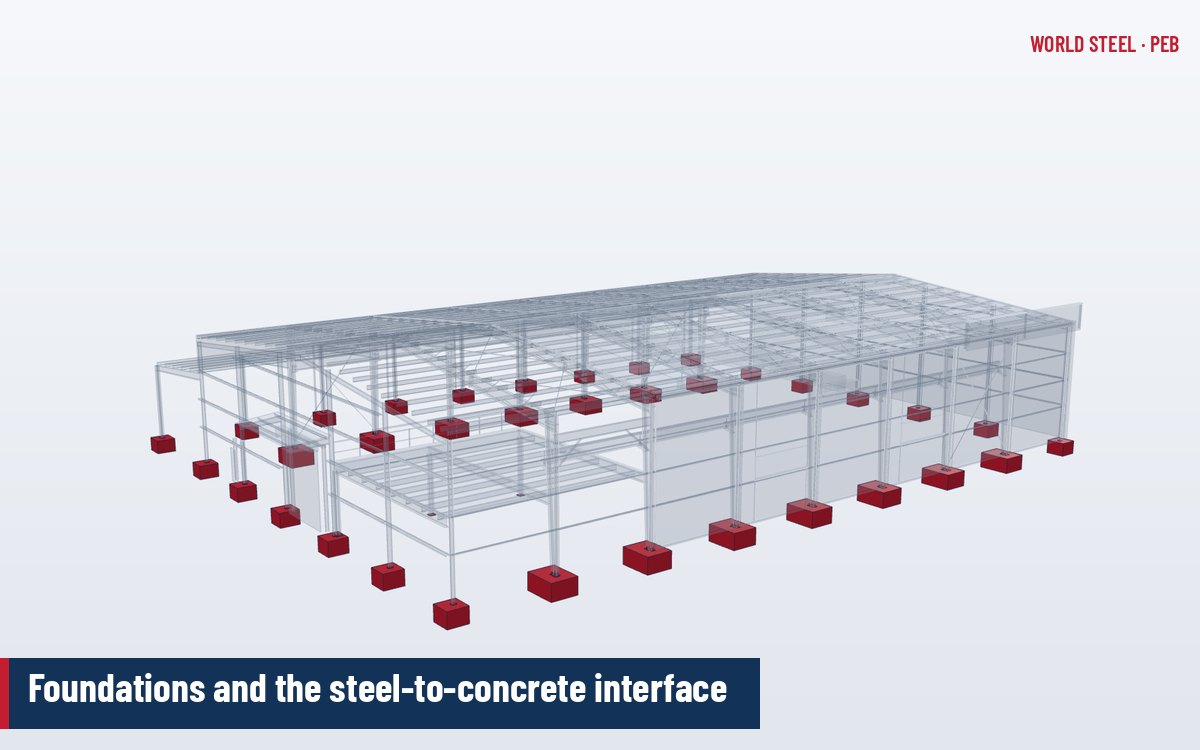
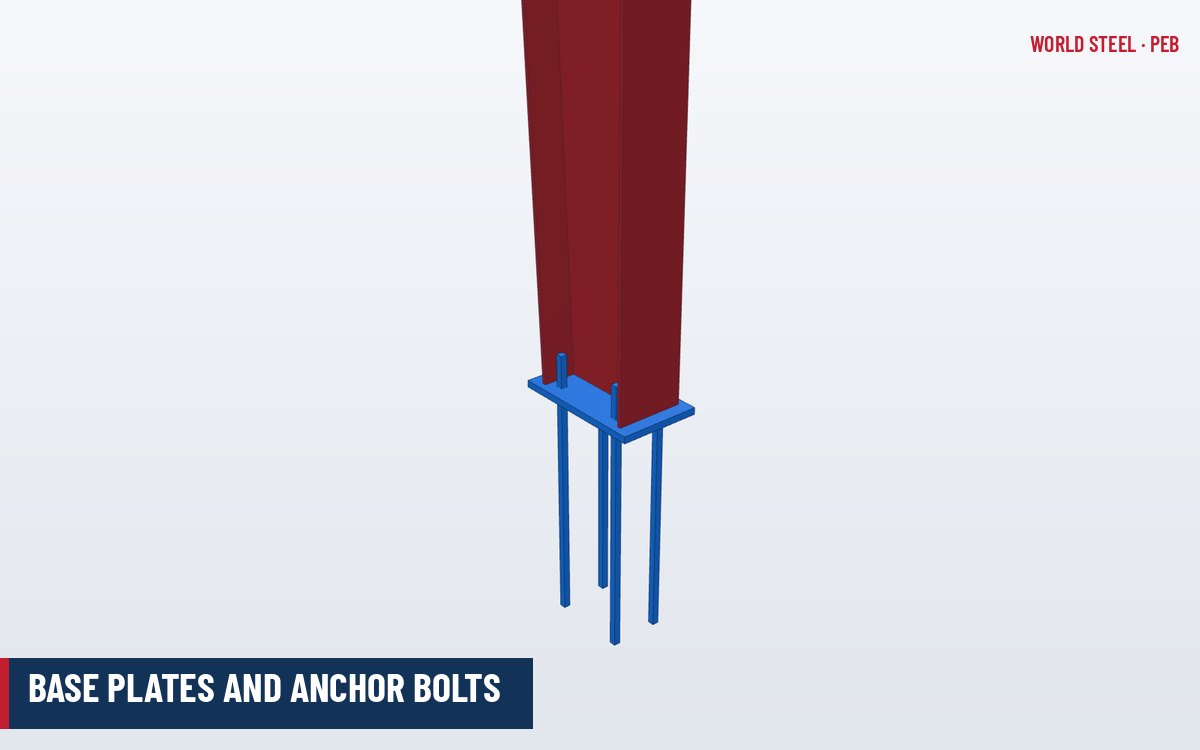
The base plate is a thick steel plate welded to the bottom of each column. Anchor bolts (anchor rods) cast into the concrete hold it down. Together they transfer the column reactions – compression, uplift tension, horizontal shear and, for fixed bases, moment – into the footing designed by others, as described in foundations and the steel-to-concrete interface.
In pre-engineered buildings most frame columns have pinned bases with two or four anchor bolts close to the web, which keeps foundations small. Fixed bases, with bolts spread outside the flanges and thicker plates, are used for crane buildings, tall eaves or tight drift requirements. The choice is made together with the column design, because it changes frame stiffness, column size and footing size at the same time.
Role in the load path
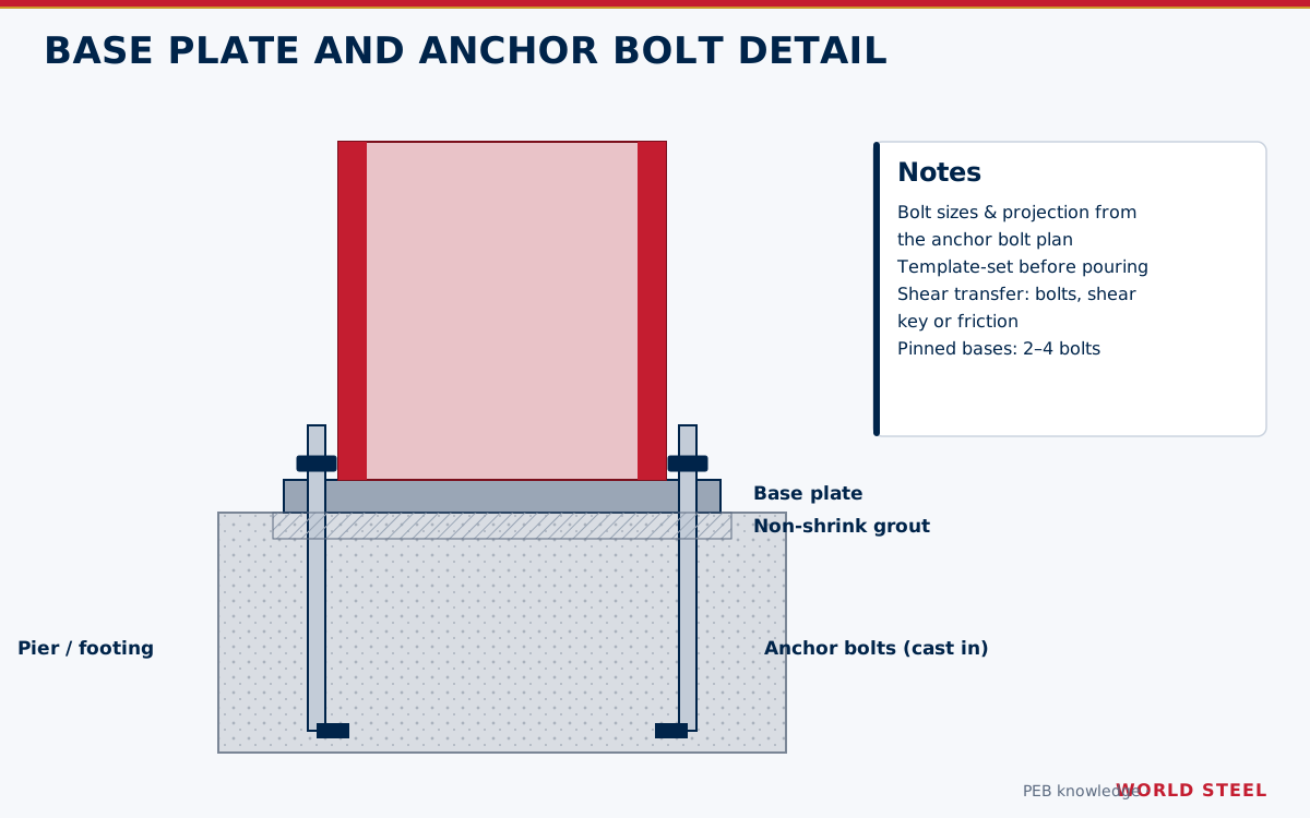
All loads collected by the frame end at the base plates. Under gravity the plate bears on grout in compression. Under wind uplift the anchor bolts are in tension. Frame thrust and longitudinal bracing forces produce horizontal shear, which is resisted by friction, by the anchor bolts in shear, or by a shear lug (shear key) welded under the plate. In braced bays the bracing reactions often govern the anchor design.
Typical sizes and materials
| Item | Pinned base | Fixed base |
|---|---|---|
| Plate thickness | 12–30 mm | 25–60 mm |
| Number of anchors | 2 or 4 | 4–8 or more |
| Anchor diameter | M20–M30 (3/4"–1-1/4") | M24–M42 (1"–1-3/4") |
| Grout thickness | 25–50 mm non-shrink grout | 25–50 mm non-shrink grout |
| Region | Standard / grade |
|---|---|
| US | ASTM F1554 Grade 36, 55 or 105 |
| Canada | ASTM F1554 or CSA G40.21 rod, design per CSA A23.3 Annex D |
| Australia / NZ | Property class 4.6 or 8.8 (AS 1110 / AS 1111 / AS/NZS 1252) |
| Europe | Property class 4.6, 5.6 or 8.8 (EN ISO 898-1) |
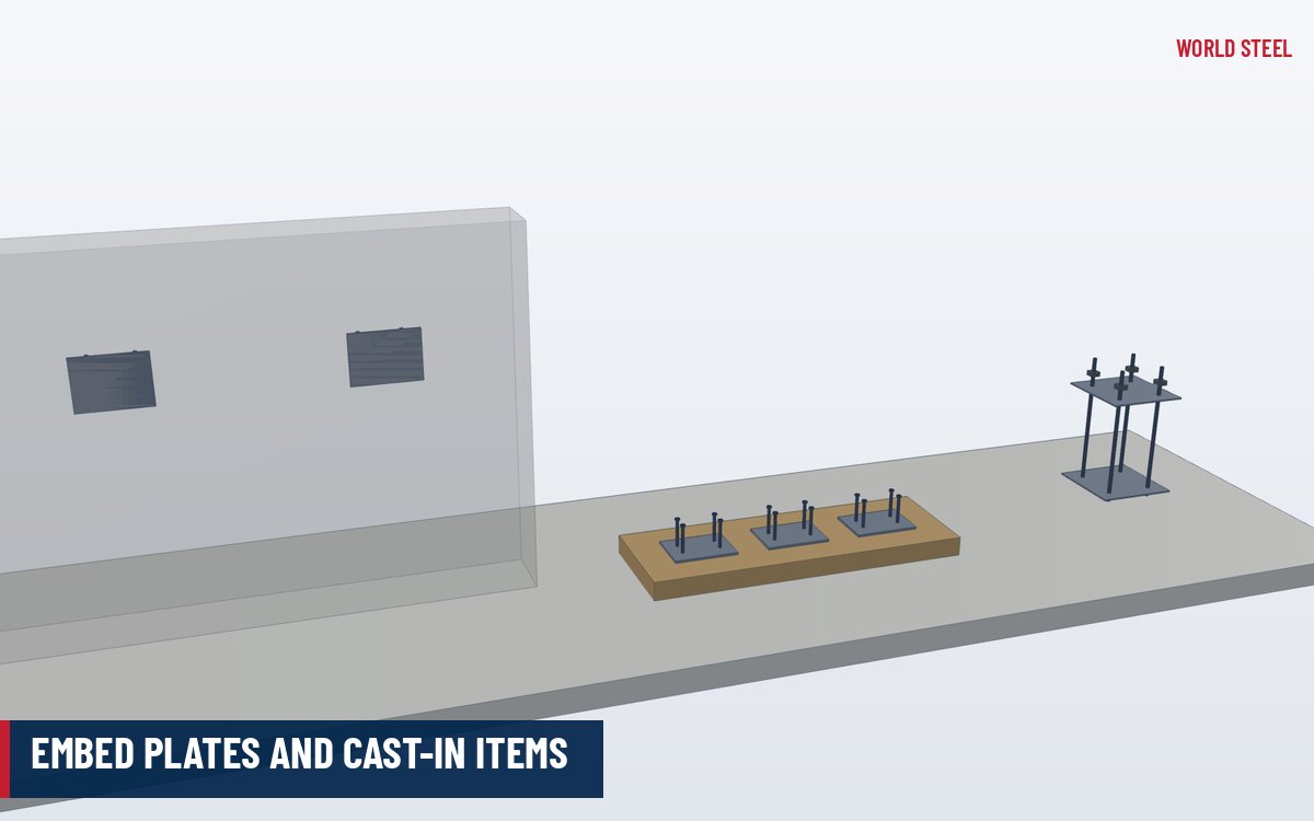
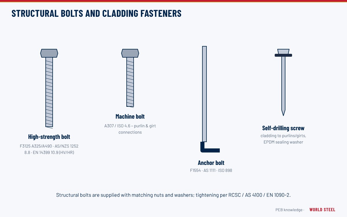
Anchors are usually hot-dip galvanised when exposed or in corrosive environments. World Steel supplies anchor bolts, nuts, plate washers and setting templates as an anchor bolt and embed package shipped ahead of the steel.
| Component | Allowance |
|---|---|
| Grout bed (or levelling nut and washer) | About 25–50 mm |
| Base plate thickness | As detailed |
| Plate washer (where shear passes through anchors) | About 6–12 mm |
| Nut (and lock nut if specified) | About one bolt diameter each |
| Thread beyond the nut | At least two to three full threads |
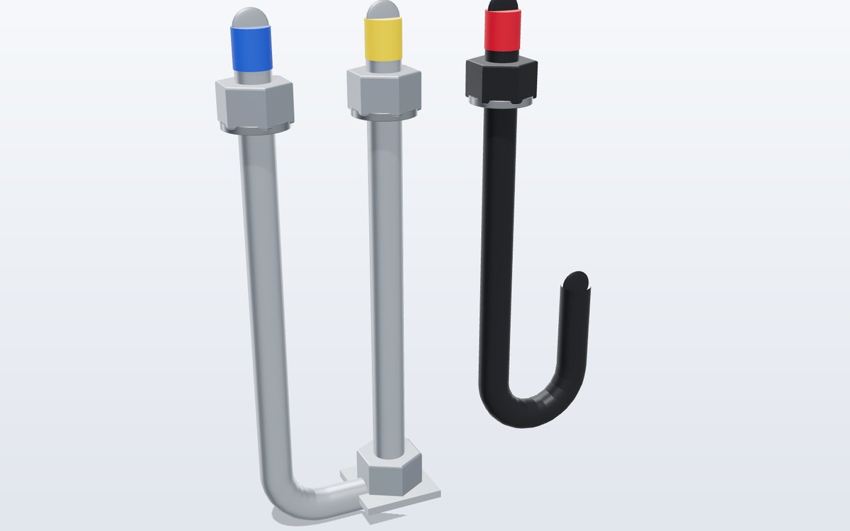
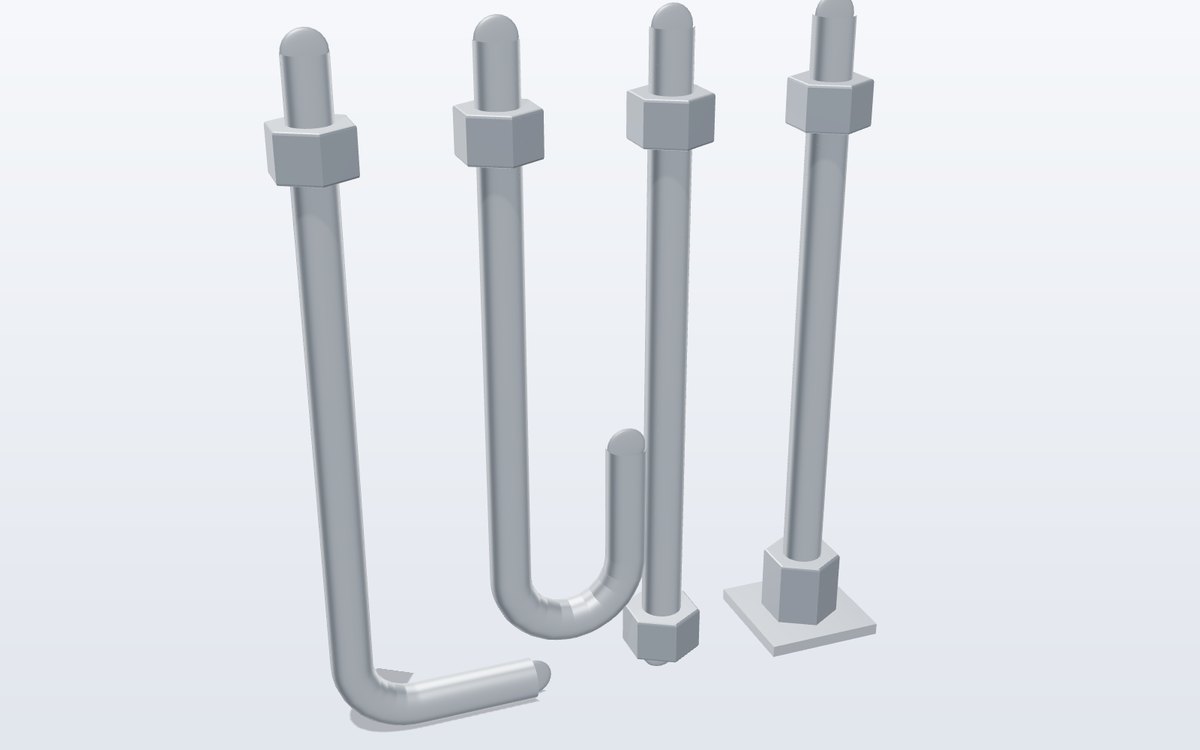
The required projection is shown on the anchor bolt plan for every bolt type. Common anchor forms are straight rods with a nut and plate washer at the embedded end, headed rods, and hooked (L or J) rods; hooked rods have limited pull-out capacity in concrete design codes and are generally reserved for low-tension locations such as endwall posts and door jambs. Secondary columns – endwall posts, door jambs and wind columns – typically use two smaller anchors and must not be forgotten on the foundation drawings. Post-installed chemical or mechanical anchors are used mainly for extensions and retrofits, designed to the same concrete anchorage codes.
Design considerations
- Plate bending from bearing pressure and bolt tension (AISC Design Guide 1 for US practice; EN 1993-1-8 for Europe).
- Anchor capacity in concrete – steel strength, concrete breakout, pull-out and side-face blowout – per ACI 318 Chapter 17, CSA A23.3 Annex D, AS 5216 or EN 1992-4.
- Shear transfer – friction is not relied on under uplift; shear lugs or hairpin reinforcement may be needed.
- Oversized holes in the base plate allow for anchor setting tolerances, with thick plate washers welded or bearing on top where shear passes through the anchors.
- Edge distances near slab edges, pits and pile caps.
Fabrication and installation
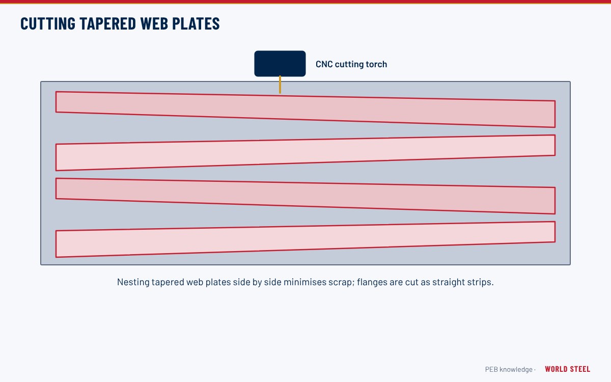
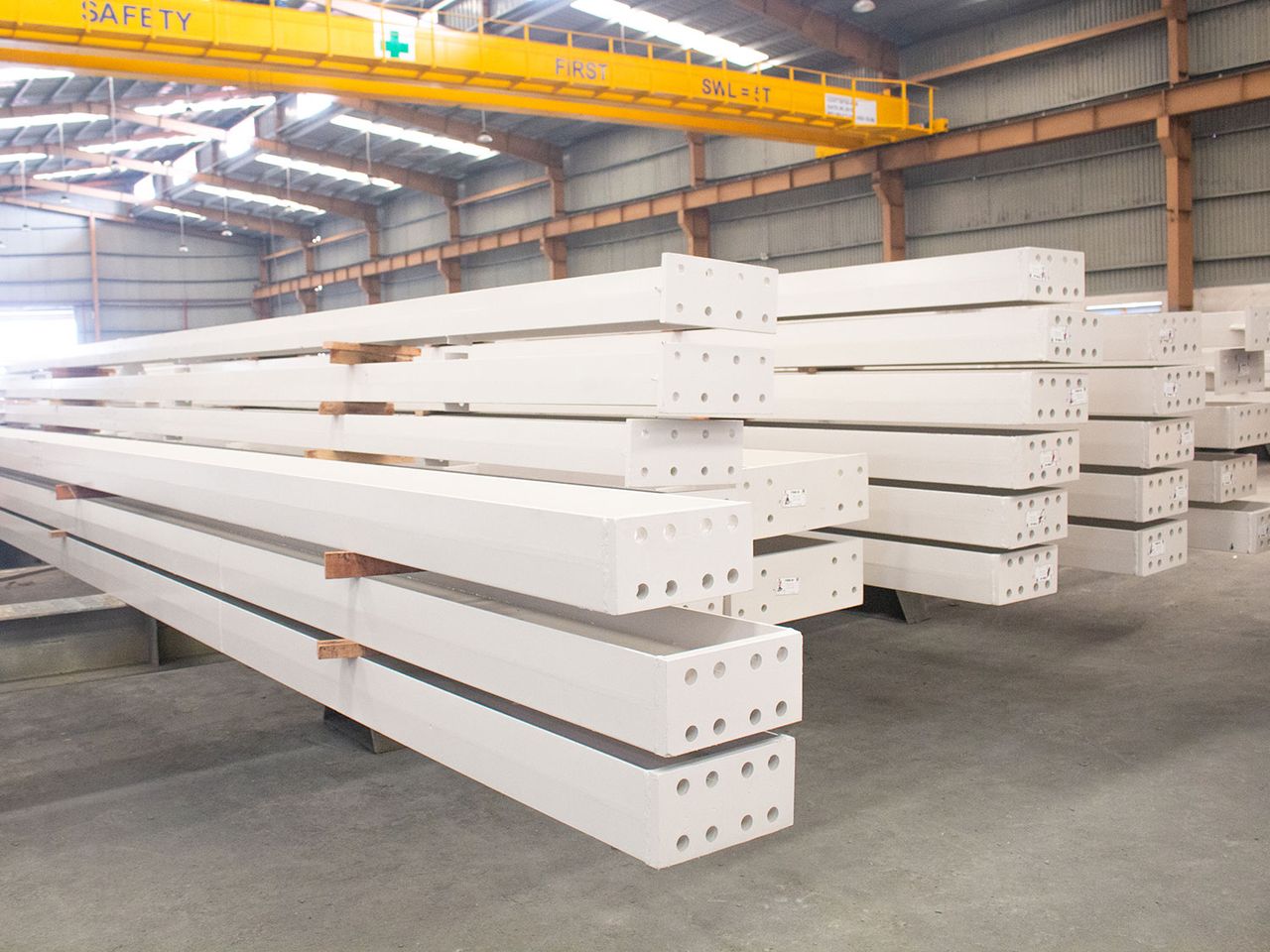
Base plates are CNC cut and drilled, then welded to the column with fillet or groove welds as designed; the plate is checked for flatness and the column for squareness. On site:
- Anchor bolts are set with a rigid template before the concrete pour and surveyed.
- Threads are protected from concrete and damage.
- Columns are set on levelling nuts or steel shims, plumbed and temporarily braced.
- Nuts are tightened; after the frame is aligned the gap is filled with non-shrink grout.
Common mistakes and quality checks
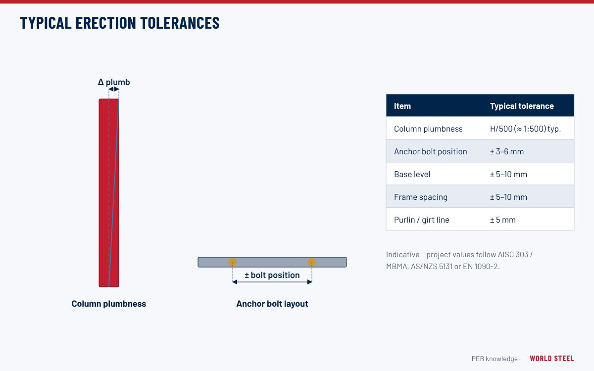
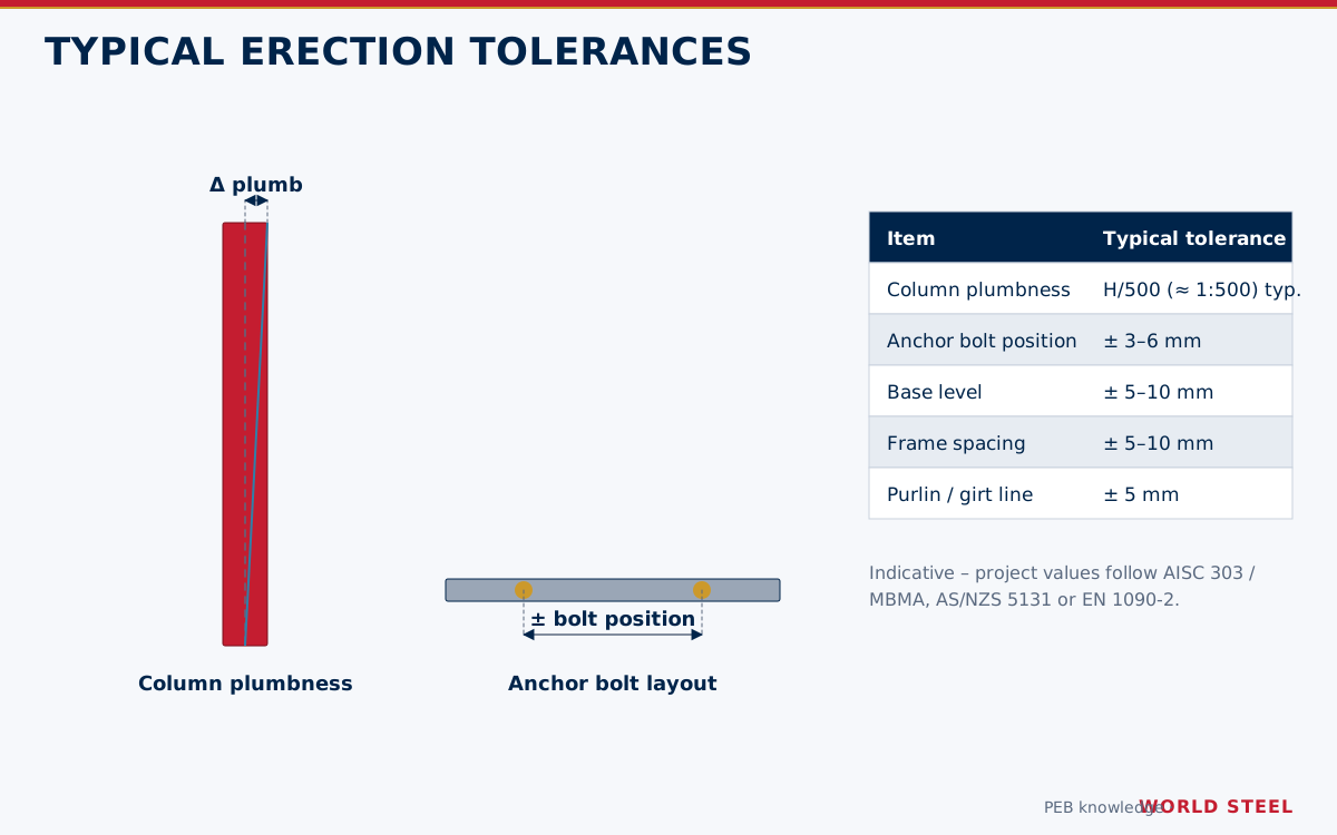
- Anchor bolts out of position beyond tolerance (for example the AISC Code of Standard Practice limits variation between rods within a group to 1/8 in) – survey before steel arrives.
- Insufficient projection to engage the full nut plus washer and levelling nut.
- Field-bending or welding anchors without the engineer's approval.
- Grout omitted or placed before final alignment.
- Shear lug pockets not formed in the footing.
Standards by region
| Region | Code | Scope |
|---|---|---|
 United States |
AISC DG 1 / ACI 318 Ch. 17 / ASTM F1554 | Base connection design and anchoring to concrete |
 Canada |
CSA S16-19 / CSA A23.3 Annex D | Steel base design and anchorage |
 Australia / NZ |
AS 4100:2020 / AS 5216 | Steel design and fastenings to concrete |
 Europe |
EN 1993-1-8 / EN 1992-4 | Column bases and fastenings in concrete |
Frequently asked questions
Who designs the anchor bolts?
The PEB supplier usually specifies anchor bolt size, layout and reactions; the foundation engineer verifies embedment and concrete capacity under the local concrete code.
Why are base plate holes oversized?
Cast-in anchors cannot be placed perfectly. Oversized holes with thick plate washers allow for setting tolerance while still transferring shear.
Can anchor bolts be supplied before the steel?
Yes. WSC ships anchor bolts and setting templates early so they can be cast while the frame is being fabricated.